Main Content

collisionVHACD

Decompose mesh into convex collision meshes using V-HACD

Since R2023b

    Description

    convexCollMeshes = collisionVHACD(sourceMesh) decomposes a triangulation mesh into convex collision meshes using a voxelized hierarchical approximate convex decomposition (V-HACD) solver.

    example

    convexCollMeshes = collisionVHACD(sourceMesh,options) specifies the solver options of the V-HACD solver.

    [convexCollMeshes,info] = collisionVHACD(___) returns information about the decomposition. in addition to the decomposed convex collision meshes, using any combination of input arguments from previous syntaxes.

    Examples

    collapse all

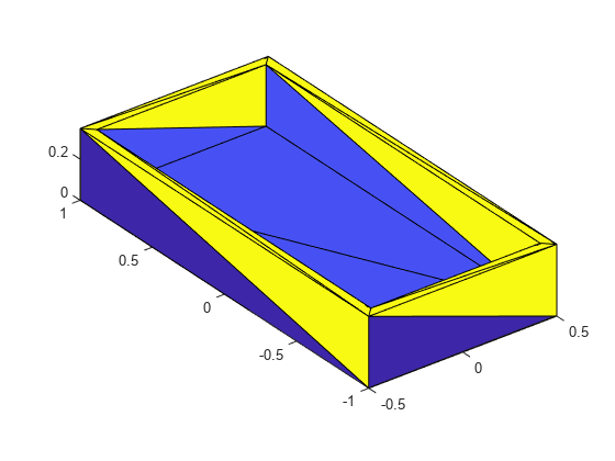
    Load an STL file containing a rectangular bin triangulation, and then visualize the bin triangulation.

    meshTri = stlread("bin.stl");
    trisurf(meshTri)
    axis equal

    Figure contains an axes object. The axes object contains an object of type patch.

    Create a collision mesh using the points from the triangulation of the bin, and then visualize the mesh. Note that, when you approximate the bin triangulation as one collision mesh, the collisionMesh object uses the convex hull of the bin triangulation to approximate the bin. As a result the collision mesh is convex, unlike the non-convex bin triangulation. The collisionMesh object does this because collision checking is most efficient with convex meshes. However, this convex approximation is not ideal for bins because robots can manipulate bins or objects inside of bins.

    meshColl = collisionMesh(meshTri.Points);
    [~,p] = show(meshColl);
    view(145,30) % Change view so it is easier to view the inside of bin
    axis equal
    hold on

    Figure contains an axes object. The axes object with xlabel X, ylabel Y contains an object of type patch.

    Create a soda can using a collision cylinder, and set the pose such that it sits in the center of the bin. Then, show it in the convex collision mesh.

    sodacan = collisionCylinder(0.1,0.4,Pose=trvec2tform([0 0 .3]));
    show(sodacan);

    Set the box to be transparent so that you can see the overlap between the bin and the soda can.

    p.FaceAlpha = 0.25;
    hold off

    Figure contains an axes object. The axes object with xlabel X, ylabel Y contains 2 objects of type patch.

    Check collision between the soda can and the convex approximation of the bin, and note that they are in collision.

    isCollidingConvex = checkCollision(sodacan,meshColl)
    isCollidingConvex = 
    1
    

    To get a better approximation of the bin for collision checking, decompose the original non-convex mesh into multiple convex meshes using voxelized hierarchical approximate convex decomposition (V-HACD).

    Use the collisionVHACD function to decompose the original non-convex triangulation into convex collision meshes. Then, show the decomposed bin with the soda can.

    decomposedBin = collisionVHACD(meshTri);
    showCollisionArray([decomposedBin {sodacan}]);
    view(145,30)
    axis equal

    Figure contains an axes object. The axes object with xlabel X, ylabel Y contains 33 objects of type patch.

    Check collision with all the meshes that approximate the bin. Note that the soda can is not in collision with the decomposed non-convex approximation of the bin. If you require a more accurate decomposition of the bin, you can specify custom solver options using the vhacdOptions object.

    isColliding = false(1,length(decomposedBin));
    for i = 1:length(decomposedBin)
        isColliding(i) = checkCollision(sodacan,decomposedBin{i});
    end
    isCollidingAll = all(isColliding)
    isCollidingAll = logical
       0


    Load the Rethink Robotics Sawyer robot.

    robot = loadrobot("rethinkSawyer",DataFormat="row")
    robot = 
      rigidBodyTree with properties:
    
         NumBodies: 20
            Bodies: {1x20 cell}
              Base: [1x1 rigidBody]
         BodyNames: {1x20 cell}
          BaseName: 'base'
           Gravity: [0 0 0]
        DataFormat: 'row'


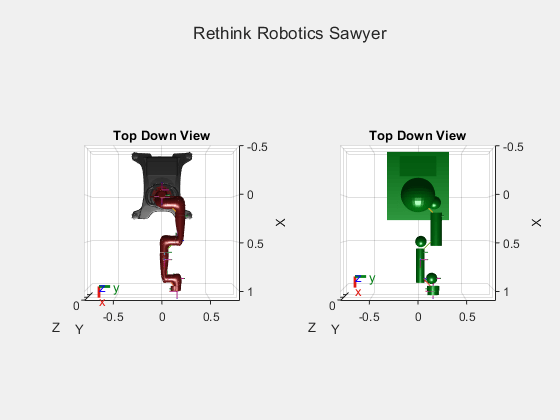
    Show the robot with just the visual meshes and show the robot with just the collision meshes. Use a vertical view so the difference between the arms is more clear.

    tiledlayout(1,2)
    sgtitle("Rethink Robotics Sawyer")
    nexttile
    show(robot,Visuals="on",Collisions="off");
    title("Top Down View")
    axis auto
    view(90,90)
    nexttile
    show(robot,Visuals="off",Collisions="on");
    title("Top Down View")
    axis auto
    view(90,90)

    Figure contains 2 axes objects. Axes object 1 with title Top Down View, xlabel X, ylabel Y contains 53 objects of type patch, line. These objects represent base, controller_box, pedestal_feet, pedestal, right_arm_base_link, right_l0, head, screen, head_camera, right_l1, right_l2, right_l3, right_l4, right_arm_itb, right_l5, right_hand_camera, right_l6, right_hand, right_wrist, right_torso_itb, torso, pedestal_mesh, right_arm_base_link_mesh, right_l0_mesh, head_mesh, screen_mesh, right_l1_mesh, right_l2_mesh, right_l3_mesh, right_l4_mesh, right_l5_mesh, right_l6_mesh, torso_mesh. Axes object 2 with title Top Down View, xlabel X, ylabel Y contains 55 objects of type patch, line. These objects represent base, controller_box, pedestal_feet, pedestal, right_arm_base_link, right_l0, head, screen, head_camera, right_l1, right_l2, right_l3, right_l4, right_arm_itb, right_l5, right_hand_camera, right_l6, right_hand, right_wrist, right_torso_itb, torso, pedestal_mesh, right_arm_base_link_mesh, right_l0_mesh, head_mesh, screen_mesh, right_l1_mesh, right_l2_mesh, right_l3_mesh, right_l4_mesh, right_l5_mesh, right_l6_mesh, torso_mesh, controller_box_coll_mesh, pedestal_feet_coll_mesh, pedestal_coll_mesh, right_arm_base_link_coll_mesh, right_l0_coll_mesh, head_coll_mesh, screen_coll_mesh, right_l1_coll_mesh, right_l2_coll_mesh, right_l3_coll_mesh, right_l4_coll_mesh, right_l5_coll_mesh, right_l6_coll_mesh, right_hand_coll_mesh.

    Note that each body of the arm is represented by a single convex mesh that does not accurately represent the physical boundaries of the arm. To achieve more accurate collision checking, you must decompose the visual meshes of the robot. The rigid body tree stores the rigid bodies of the arm at indices 9 to 17.

    First, create V-HACD solver options for individual mesh decompositions with the maximum number of convex hulls set to 10.

    opts = vhacdOptions("IndividualMesh",MaxNumConvexHulls=10);

    Then for each rigid body:

    1. Get the current rigid body and clear the current collision mesh.

    2. Get the corresponding visual data if there is any.

    3. If there is visual data, use collisionVHACD (Robotics System Toolbox) with the custom solver options to decompose the triangulation of the visual data into an array of collision meshes.

    4. Add each collision mesh from the array of collision meshes to the rigid body.

    for bodyIdxToReplace = 9:17
        % 1. Get current body and clear collision mesh
        currBody = robot.Bodies{bodyIdxToReplace};
        clearCollision(currBody);
    
        % 2. Get Corresponding visual data
        vizData = getVisual(robot.Bodies{bodyIdxToReplace});
    
        % 3. If visual data, decompose visual data
        if ~isempty(vizData)
            collisionArray = collisionVHACD(vizData(1).Triangulation,opts);
    
            % 4. Add each collision mesh to the rigid body
            for j = 1:numel(collisionArray)
                addCollision(currBody,collisionArray{j});
            end
        end
    end

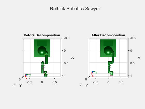
    Show the original collision meshes of the robot arm next to the updated collision mesh of the arm.

    tiledlayout(1,2);
    sgtitle("Rethink Robotics Sawyer")
    nexttile
    robotOriginal = loadrobot("rethinkSawyer",DataFormat="row");
    show(robotOriginal,Visuals="off",Collisions="on");
    title("Before Decomposition")
    axis auto
    view(90,90)
    nexttile
    show(robot,Visuals="off",Collisions="on");
    title("After Decomposition")
    view(90,90)
    axis auto

    Figure contains 2 axes objects. Axes object 1 with title Before Decomposition, xlabel X, ylabel Y contains 55 objects of type patch, line. These objects represent base, controller_box, pedestal_feet, pedestal, right_arm_base_link, right_l0, head, screen, head_camera, right_l1, right_l2, right_l3, right_l4, right_arm_itb, right_l5, right_hand_camera, right_l6, right_hand, right_wrist, right_torso_itb, torso, pedestal_mesh, right_arm_base_link_mesh, right_l0_mesh, head_mesh, screen_mesh, right_l1_mesh, right_l2_mesh, right_l3_mesh, right_l4_mesh, right_l5_mesh, right_l6_mesh, torso_mesh, controller_box_coll_mesh, pedestal_feet_coll_mesh, pedestal_coll_mesh, right_arm_base_link_coll_mesh, right_l0_coll_mesh, head_coll_mesh, screen_coll_mesh, right_l1_coll_mesh, right_l2_coll_mesh, right_l3_coll_mesh, right_l4_coll_mesh, right_l5_coll_mesh, right_l6_coll_mesh, right_hand_coll_mesh. Axes object 2 with title After Decomposition, xlabel X, ylabel Y contains 108 objects of type patch, line. These objects represent base, controller_box, pedestal_feet, pedestal, right_arm_base_link, right_l0, head, screen, head_camera, right_l1, right_l2, right_l3, right_l4, right_arm_itb, right_l5, right_hand_camera, right_l6, right_hand, right_wrist, right_torso_itb, torso, pedestal_mesh, right_arm_base_link_mesh, right_l0_mesh, head_mesh, screen_mesh, right_l1_mesh, right_l2_mesh, right_l3_mesh, right_l4_mesh, right_l5_mesh, right_l6_mesh, torso_mesh, controller_box_coll_mesh, pedestal_feet_coll_mesh, pedestal_coll_mesh, right_arm_base_link_coll_mesh, right_l0_coll_mesh, head_coll_mesh, screen_coll_mesh, right_l1_coll_mesh, right_l2_coll_mesh, right_l3_coll_mesh, right_l4_coll_mesh, right_l5_coll_mesh, right_l6_coll_mesh.

    Note that in this case the new collision meshes represent the robot arm more accurately.

    Input Arguments

    collapse all

    Triangulation of mesh geometry to decompose, specified as a triangulation object.

    For visualizing triangulations of meshes before decomposition, you can use the trimesh or trisurf function.

    V-HACD solver options, specified as a vhacdOptions object.

    You must set the Type property of the vhacdOptions object to "IndividualMesh" to specify custom V-HACD options for the collisionVHACD function. If the Type property is set to "RigidBodyTree", then you can only use the vhacdOptions object for importing rigid body trees using the importrobot (Robotics System Toolbox) function

    Output Arguments

    collapse all

    Convex collision meshes, returned as an N-element cell array of collisionMesh objects.

    You can use the showCollisionArray (Robotics System Toolbox) function to visualize the collision meshes.

    Decomposition solution information, returned as a structure containing these fields:

    • SourceVolume — Volume of the input source mesh specified by the sourceMesh argument.

    • CompositeDecompVolume — Total combined volume of the output convex collision meshes. This total includes the volume of overlapping meshes.

    • RawDataN-element cell array of mesh vertices used to generate the collision array. N is the total number of collision objects needed to represent the decomposed mesh.

    References

    [1] Mammou, Khaled, et al. “Voxelized Hierarchical Approximate Convex Decomposition - V-HACD Version 4.” GitHub, October 24, 2022. https://github.com/kmammou/v-hacd.

    Version History

    Introduced in R2023b