ecompass
Orientation from magnetometer and accelerometer readings
Syntax
Description
The ecompass function computes the orientation of a
sensor using magnetometer and accelerometer readings to rotate quantities from a global
coordinate system to a body coordinate system.
orientation = ecompass(accelerometerReading,magnetometerReading)quaternion that
can rotate quantities from a parent (NED) frame to a child (sensor) frame.
orientation = ecompass(accelerometerReading,magnetometerReading,orientationFormat)quaternion or rotation
matrix.
orientation = ecompass(accelerometerReading,magnetometerReading,orientationFormat,'ReferenceFrame',RF)RF of the
orientation output.
Examples
Input Arguments
Output Arguments
Algorithms
The ecompass function returns a quaternion or rotation matrix
that can rotate quantities from a parent (NED for example) frame to a child (sensor)
frame. For both output orientation formats, the rotation operator is determined by
computing the rotation matrix.
The rotation matrix is first calculated with an intermediary:
and then normalized column-wise. a and m are the
accelerometerReading input and the
magnetometerReading input, respectively.
To understand the rotation matrix calculation, consider an arbitrary point on the Earth and its corresponding local NED frame. Assume a sensor body frame, [x,y,z], with the same origin.
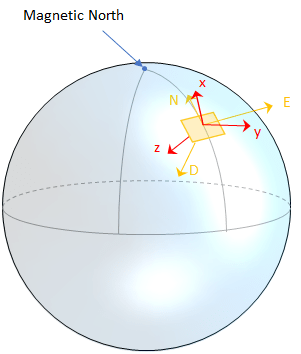
Recall that orientation of a sensor body is defined as the rotation operator (rotation matrix or quaternion) required to rotate a quantity from a parent (NED) frame to a child (sensor body) frame:
where
R is a 3-by-3 rotation matrix, which can be interpreted as the orientation of the child frame.
pparent is a 3-by-1 vector in the parent frame.
pchild is a 3-by-1 vector in the child frame.
For a stable sensor body, an accelerometer returns the acceleration due to gravity. If the sensor body is perfectly aligned with the NED coordinate system, all acceleration due to gravity is along the z-axis, and the accelerometer reads [0 0 1]. Consider the rotation matrix required to rotate a quantity from the NED coordinate system to a quantity indicated by the accelerometer.
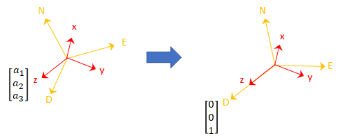
The third column of the rotation matrix corresponds to the accelerometer reading:
A magnetometer reading points toward magnetic north and is in the N-D plane. Again, consider a sensor body frame aligned with the NED coordinate system.
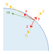
By definition, the E-axis is perpendicular to the N-D plane, therefore D ⨯ N = E, within some amplitude scaling. If the sensor body frame is aligned with NED, both the acceleration vector from the accelerometer and the magnetic field vector from the magnetometer lie in the N-D plane. Therefore a ⨯ m = y, again with some amplitude scaling.
Consider the rotation matrix required to rotate NED to the child frame, [x y z].
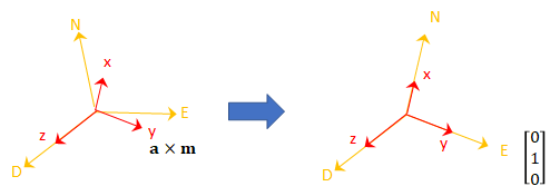
The second column of the rotation matrix corresponds to the cross product of the accelerometer reading and the magnetometer reading:
By definition of a rotation matrix, column 1 is the cross product of columns 2 and 3:
Finally, the rotation matrix is normalized column-wise:
Note
The ecompass algorithm uses magnetic north, not true north,
for the NED coordinate system.
References
[1] Open Source Sensor Fusion. https://github.com/memsindustrygroup/Open-Source-Sensor-Fusion/tree/master/docs
Extended Capabilities
Version History
Introduced in R2018b
