Implement Online Simultaneous Localization And Mapping (SLAM) with Lidar Scans
This example demonstrates how to implement the Simultaneous Localization And Mapping (SLAM) algorithm on lidar scans obtained from simulated environment using pose graph optimization. This example requires Simulink® 3D Animation™ and Navigation Toolbox™.
The goal of this example is to build a map of the environment using the lidar scans and retrieve the trajectory of the robot, with the robot simulator in the loop.
The basics of SLAM algorithm can be found in the Implement Simultaneous Localization And Mapping (SLAM) with Lidar Scans example.
Load Trajectory of the Robot from File
The robot trajectory are waypoints given to the robot to move in the simulated environment. For this example, the robot trajectory is provided for you.
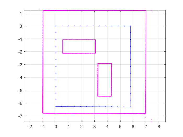
load slamRobotTrajectory.matA floor plan and approximate path of the robot are provided for illustrative purposes. This image shows the environment being mapped and the approximate trajectory of the robot.
Load and View the Virtual World
This example uses a virtual scene with two vehicles and four walls as obstacles and a robot equipped with a lidar scanner shown in the Simulink 3D Animation Viewer. You can navigate in a virtual scene using the menu bar, toolbar, navigation panel, mouse, and keyboard.
Create and open the vrworld object.
w = vrworld('slamSimulatedWorld.x3d');
open(w)
Create a figure showing the virtual scene
vrf = vrfigure(w)

vrf =

	vrfigure object: 1-by-1

	Differential Wheeled Robot with LIDAR Sensor
Initialize the Robot Position and Rotation in Virtual World
The virtual scene is represented as the hierarchical structure of a VRML file used by Simulink 3D Animation. The position and orientation of child objects is relative to the parent object. The robot vrnode is used to manipulate the position and orientation of the robot in the virtual scene.
To access a VRML node, an appropriate vrnode object must be created. The node is identified by its name and the world it belongs to.
Create vrnode handle for robot in virtual environment.
robotVRNode = vrnode(w,'Robot');Set the initial position of the robot from the trajectory first point and set the initial rotation to 0 rad about y axis.
robotVRNode.children.translation = [trajectory(1,1) 0 trajectory(1,2)];
robotVRNode.children.rotation = [0 1 0 0];
Create handle for lidar sensor on robot by creating vrnode.
lidarVRNode = vrnode(w,'LIDAR_Sensor');The simulated lidar is using total 240 laser lines and the angle between these lines is 1.5 degree.
angles  = 180:-1.5:-178.5;
angles = deg2rad(angles)';
Waiting to update and initialize virtual scene
pause(1)
Create Lidar Slam Object
Create a lidarSLAM object and set the map resolution and the max lidar range. This example uses a simulated virtual environment. The robot in this vrworld has a lidar sensor with range of 0 to 10 meters. Set the max lidar range (8m) smaller than the max scan range, as the laser readings are less accurate near max range. Set the grid map resolution to 20 cells per meter, which gives a 5cm precision. These two parameters are used throughout the example.
maxLidarRange = 8;
mapResolution = 20;
slamAlg = lidarSLAM(mapResolution,maxLidarRange);
The loop closure parameters are set empirically. Using a higher loop closure threshold helps reject false positives in loop closure identification process. Keep in mind that a high-score match may still be a bad match. For example, scans collected in an environment that has similar or repeated features are more likely to produce false positive. Using a higher loop closure search radius allows the algorithm to search a wider range of the map around the current pose estimate for loop closures.
slamAlg.LoopClosureThreshold = 200;
slamAlg.LoopClosureSearchRadius = 3;
controlRate = rateControl(10);
Observe the Effect of Loop Closure and Optimization Process
Create a loop to navigate the robot through the virtual scene. The robot position is updated in the loop from the trajectory points. The scans are obtained from the robot as robot navigates through the environment.
Loop closures are automatically detected as the robot moves. The pose graph optimization is performed whenever a loop closure is detected. This can be checked using the output optimizationInfo.IsPerformed value from addScan.
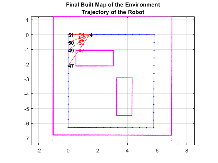
A snapshot is shown to demonstrate of the scans and poses when the first loop closure is identified and verify the results visually. This plot shows overlaid scans and an optimized pose graph for the first loop closure.
The final built map would be presented after all the scans are collected and processed.
The plot is updated continuously as robot navigates through virtual scene
firstLoopClosure = false;
scans = cell(length(trajectory),1);

figure
for i=1:length(trajectory)
    % Use translation property to move the robot.
    robotVRNode.children.translation = [trajectory(i,1) 0 trajectory(i,2)];
    vrdrawnow;

    % Read the range readings obtained from lidar sensor of the robot.
    range = lidarVRNode.pickedRange;

    % The simulated lidar readings will give -1 values if the objects are
    % out of range. Make all these value to the greater than
    % maxLidarRange.
    range(range==-1) = maxLidarRange+2;

    % Create a lidarScan object from the ranges and angles.
    scans{i} = lidarScan(range,angles);

    [isScanAccepted,loopClosureInfo,optimizationInfo] = addScan(slamAlg,scans{i});
    if isScanAccepted
        % Visualize how scans plot and poses are updated as robot navigates
        % through virtual scene
        show(slamAlg);

        % Visualize the first detected loop closure
        % firstLoopClosure flag is used to capture the first loop closure event
        if optimizationInfo.IsPerformed && ~firstLoopClosure
            firstLoopClosure = true;
            show(slamAlg,'Poses','off');
            hold on;
            show(slamAlg.PoseGraph);
            hold off;
            title('First loop closure');
            snapnow
        end
    end

    waitfor(controlRate);
end

Plot the final built map after all scans are added to the slamAlg object.
show(slamAlg,'Poses','off');
hold on
show(slamAlg.PoseGraph);
hold off
title({'Final Built Map of the Environment','Trajectory of the Robot'});

Build Occupancy Grid Map
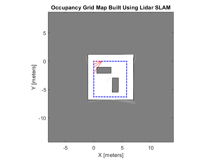
The optimized scans and poses can be used to generate a occupancyMap which represents the environment as a probabilistic occupancy grid.
[scans,optimizedPoses]  = scansAndPoses(slamAlg);
map = buildMap(scans,optimizedPoses,mapResolution,maxLidarRange);
Visualize the occupancy grid map populated with the laser scans and the optimized pose graph.
figure;
show(map);
hold on
show(slamAlg.PoseGraph,'IDs','off');
hold off
title('Occupancy Grid Map Built Using Lidar SLAM');

Close the virtual scene.
close(vrf);
close(w);
delete(w);
See Also
poseGraph | lidarSLAM | occupancyMap
