Simulate RGB-D Visual SLAM System with Cosimulation in Gazebo and Simulink
Visual simultaneous localization and mapping (vSLAM) often uses a single monocular camera that relies on RGB images. Such single camera setups have limited scale accuracy and depth perception. Integrating a depth camera alongside a monocular camera provides direct measurements of scene geometry, eliminates scale ambiguity, and significantly improves the mapping accuracy. This setup is referred to as an RGB-D visual SLAM system.
This example uses a Gazebo world which contains a Pioneer robot mounted with an RGB-D camera, in cosimulation with Simulink®. It shows how to use the RGB and depth images from the robot to simulate an RGB-D visual SLAM system in Simulink. Cosimulation enables you to control the time stepping in Gazebo using Simulink, and provides time-synchronized RGB and depth images, which are crucial for the accuracy of RGB-D SLAM. Because this is an indoor scene, it is a good candidate for RGB-D cameras, which have limited depth perception and are sensitive to lighting conditions.
Connect to Remote Device Running Gazebo
For this example, download a virtual machine (VM) using the instructions in Get Started with Gazebo and Simulated TurtleBot (ROS Toolbox), and then follow these steps.
Disable accelerated 3D graphics for the VM. In the VMware Player app, go to Virtual Machine Settings > Display > 3D Graphics and clear Accelerate 3D Graphics. This step is crucial for the synchronized time stepping between Gazebo and Simulink.
Start the Ubuntu® virtual machine.
On the Ubuntu desktop, click the Gazebo RGBD SLAM ROS icon to start the Gazebo world built for this example.
If you are using a custom scene on a different remote device, you must first install the Gazebo cosimulation plugin before you run the example. For more information about installing the plugin, see Perform Co-Simulation Between Simulink and Gazebo (Robotics System Toolbox).

Load and Set Up Simulation Data
Load and visualize the recorded waypoints for the ground truth trajectory of the robot.
load("rgbdvslamWaypoints.mat")
plot(wayPoints(:,1),wayPoints(:,2),LineWidth=3)
xlabel("X")
ylabel("Y")
grid on
title("Robot Ground Truth Trajectory in World Frame")

Specify the simulation sample time.
Ts = 0.05;
Calculate the end time of the simulation based on the sample time and number of waypoints in the trajectory.
simEndTime = (size(wayPoints,1)-1)*Ts
simEndTime =
12.5500
Inspect Simulink Model
The model implements the RGB-D visual SLAM system and cosimulation with Gazebo to control the robot motion. It also visualizes images from the RGB-D sensor and logs the camera poses and view IDs generated from the visual SLAM system. The model contains these components:
The Gazebo Pacer (Robotics System Toolbox) block advances the Gazebo simulation at the same rate as Simulink, which enables you to execute commands accurately while simulating the physical dynamics in Gazebo. To use this model with your own ROS device running Gazebo, you must update the cosimulation network parameters by clicking Configure Gazebo network and simulation settings in the block mask.
The Gazebo Read (Robotics System Toolbox) blocks obtain the RGB and depth image messages from Gazebo.
The MATLAB Function block
getImagesFromGazeboMsgsprocesses the messages from Gazebo and outputs the RGB image and depth image as auint8matrix and auint16matrix, respectively.The MATLAB System block
HelperRGBDVisualSLAM Systemimplements the RGB-D visual SLAM algorithm using thergbdvslam(Computer Vision Toolbox) object and its object functions, and outputs the camera poses and view IDs. You can use the block parameters to change the visual SLAM parameters.The
LoggingandVisualizationsubsystem logs the final camera poses and view IDs from the visual SLAM run at the final timestep. It also visualizes the RGB and depth images of detected key frames during the simulation.The
RobotNavigationsubsystem controls the robot motion in Gazebo along the input waypoints using Gazebo Apply Command (Robotics System Toolbox) blocks.
open_system("rgbdvslamGazeboCosim")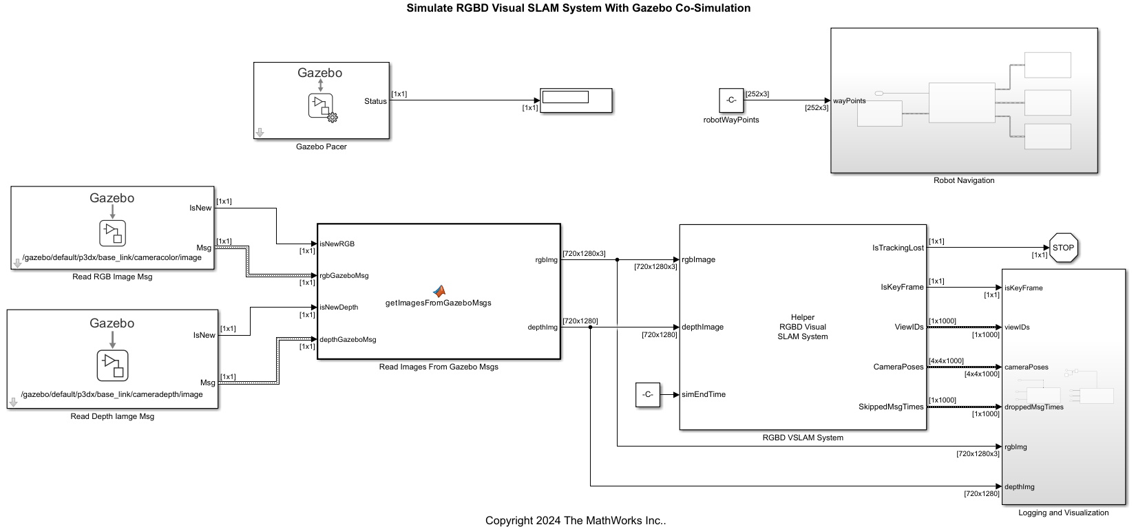
Run RGB-D Visual SLAM Simulation
Run the model. The robot moves in Gazebo, and the model initializes the map and starts running the RGB-D visual SLAM algorithm.
The Video Viewer visualizes the RGB and depth images throughout the simulation.
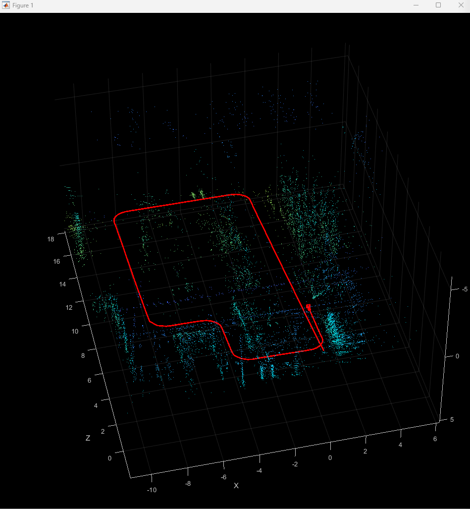
The figure window visualizes the 3-D map points and the camera trajectory throughout the simulation.
At the final time step, the model saves the camera poses, view IDs, as well as the time steps of any messages dropped during the simulation.
out = sim("rgbdvslamGazeboCosim");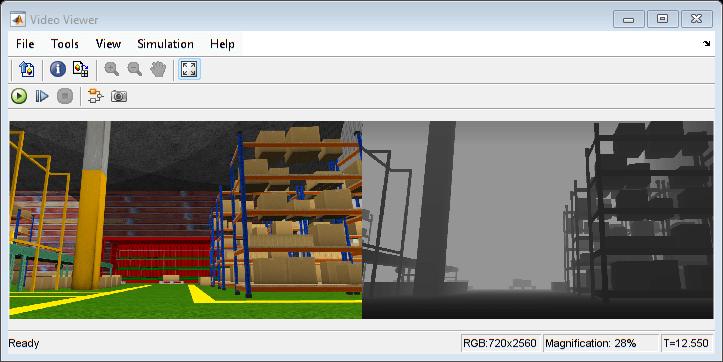
Compare Results with Ground Truth
Use the helperProcessRGBDVSLAMResults helper function to get the camera poses and ground truth waypoints as rigidtform3d objects. The function synchronizes the camera poses with the exact ground truth waypoint poses at each time step by filtering out the waypoints where the Simulink-Gazebo communication dropped messages.
[camPosesEst,camPosesGT] = helperProcessRGBDVSLAMResults(out,wayPoints,Ts);
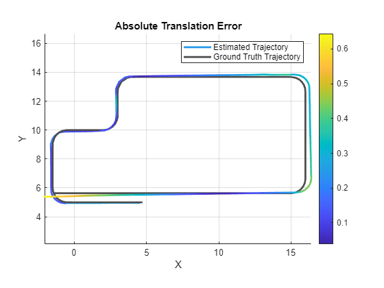
Use the compareTrajectories function to calculate and visualize the absolute translation error between the estimated and ground truth camera poses.
Note that the ground truth camera poses are in the world frame, but the estimated camera poses are in the camera frame. The compareTrajectories (Computer Vision Toolbox) function aligns the estimated trajectory to the ground truth trajectory by performing a least-square fitting between the translation components of poses in the two trajectories. Use the trajectory metrics object to display the root mean squared error (RMSE) between the estimated and ground truth camera translations.
metrics = compareTrajectories(camPosesEst,camPosesGT,AlignmentType="rigid");
figure
plot(metrics,"absolute-translation",ShowGroundTruth=true);
disp(["Absolute RMSE for waypoint location (m): ",num2str(metrics.AbsoluteRMSE(2))]);
Absolute RMSE for waypoint location (m): 0.27895
view(0,90)
See Also
rgbdvslam (Computer Vision Toolbox)
Topics
- Build and Deploy Visual SLAM Algorithm with ROS in MATLAB
- Visual SLAM with RGB-D Camera (Computer Vision Toolbox)
- Performant and Deployable Stereo Visual SLAM with Fisheye Images (Computer Vision Toolbox)