Main Content

fegeometry

Geometry object for finite element analysis

Since R2023a

Description

An fegeometry object contains a geometry for use in a finite element analysis with an femodel object.

Creation

Description

gm = fegeometry(geometry) creates an fegeometry object that you can use in a finite element analysis with an femodel object. Alternatively, you can assign a geometry directly to the Geometry property of femodel, for example, femodel.Geometry = geometry.

example

gm = fegeometry(geometry,Name=Value) creates an fegeometry object using one or more name-value arguments. For this syntax, geometry must specify a path to an STL or STEP file.

example

gm = fegeometry(mesh) creates an fegeometry object from a mesh represented by an FEMesh object. If the mesh data identifies multiple faces for a 2-D geometry or multiple cells for a 3-D geometry, the resulting geometry contains corresponding multiple faces or cells.

example

gm = fegeometry(nodes,elements) creates an fegeometry object from a mesh represented by nodes and elements.

example

gm = fegeometry(___,ElementIDToRegionID) creates a multidomain geometry from a mesh represented by an FEMesh object or by nodes and elements. ElementIDToRegionID specifies the domain IDs for each element of the mesh.

example

Input Arguments

expand all

Geometry description, specified as one of these values:

  • String scalar or character vector that contains a path to an STL or STEP file. The path must end with the file extension ".stl", ".STL", ".stp", ".STP", ".step", ".STEP", or any combination of uppercase and lowercase letters in this extension.

  • Decomposed geometry matrix or a handle to a geometry function. For details about a decomposed geometry matrix, see decsg. A geometry function must return the same result for the same input arguments in every function call. Thus, it must not contain functions and expressions designed to return a variety of results, such as random number generators.

  • triangulation object. The fegeometry function accepts both surface triangulation and triangulation with tetrahedra for 3-D geometries. For a 3-D geometry created from surface triangulation, the Mesh property remains empty. For a 2-D geometry or a 3-D geometry created from triangulation with tetrahedra, fegeometry uses triangulation points and connectivity list to specify a linear mesh. If the Mesh property is empty or your task requires a more accurate quadratic mesh or a finer linear mesh, use the generateMesh function.

  • delaunayTriangulation object. The fegeometry function uses triangulation points to specify a mesh. If your task requires a more accurate quadratic mesh, use the generateMesh function.

  • DiscreteGeometry object.

  • AnalyticGeometry object.

Since R2024b

Mesh description, specified as an FEMesh object.

Mesh nodes, specified as an Nnodes-by-2 or Nnodes-by-3 matrix for a 2-D or 3-D geometry, respectively. Nnodes is the number of nodes in the mesh. Each row of the matrix contains x-, y-, and, if applicable, z- coordinates of one node.

Data Types: double

Mesh elements, specified as an integer matrix with Nelements rows and 3, 4, 6, or 10 columns, where Nelements is the number of elements in the mesh.

  • Linear planar mesh or linear mesh on the geometry surface has size Nelements-by-3. Each row of elements contains the indices of the triangle corner nodes for a surface element. In this case, the resulting geometry does not contain a full mesh. Create the mesh using the generateMesh function.

  • Linear elements have size Nelements-by-4. Each row of elements contains the indices of the tetrahedral corner nodes for an element.

  • Quadratic planar mesh or quadratic mesh on the geometry surface has size Nelements-by-6. Each row of elements contains the indices of the triangle corner nodes and edge centers for a surface element. In this case, the resulting geometry does not contain a full mesh. Create the mesh using the generateMesh function.

  • Quadratic elements have size Nelements-by-10. Each row of elements contains the indices of the tetrahedral corner nodes and the tetrahedral edge midpoint nodes for an element.

For details on node numbering for linear and quadratic elements, see Mesh Data.

Data Types: double

Domain information for each mesh element, specified as a vector of positive integers. Each vector element is an ID of a geometric region for an element of the mesh. The length of this vector equals the number of elements in the mesh.

Data Types: double

Name-Value Arguments

Specify optional pairs of arguments as Name1=Value1,...,NameN=ValueN, where Name is the argument name and Value is the corresponding value. Name-value arguments must appear after other arguments, but the order of the pairs does not matter.

Example: gm = fegeometry("AngleBlock.step",MaxRelativeDeviation=5) imports a geometry from the AngleBlock.step file using the relative sag of 5.

Since R2024a

Indicator to allow the import of a self-intersecting geometry from an STL or STEP file, specified as true or false. You also can use 1 or 0 instead of true or false. By default, fegeometry does not check for self-intersections and lets you import these types of geometries. If you set this argument to false or 0, fegeometry issues an error for a geometry with self-intersections.

Example: AllowSelfIntersections=true

Since R2024a

Threshold for the dihedral angle between adjacent triangles to indicate the edge and create two separate faces, specified as a number between 10 and 90. The specified FeatureAngle value represents degrees. This argument works only for importing a geometry from an STL file.

If the angle between the triangles exceeds the threshold, the edge becomes a topological (feature) edge separating two faces. If the angle does not exceed the threshold, fegeometry does not create a topological edge with two separate faces, unless the function can create the edge based on other criteria. Instead, fegeometry creates one face.

Example: FeatureAngle=30

Relative sag for importing a STEP geometry, specified as a number in the range [0.1,10]. This value controls the accuracy of the geometry import from a STEP file. A relative sag is the ratio between the local absolute sag and the local mesh edge length. The absolute sag is the maximal gap between the mesh and the geometry.

Gap between the curved geometry edge and the straight mesh edge represents the local absolute sag.

Example: MaxRelativeDeviation=5

Data Types: double

Properties

expand all

This property is read-only.

Number of geometry cells, returned as a nonnegative integer.

Data Types: double

This property is read-only.

Number of geometry faces, returned as a positive integer.

Data Types: double

This property is read-only.

Number of geometry edges, returned as a nonnegative integer.

Data Types: double

This property is read-only.

Number of geometry vertices, returned as a nonnegative integer.

Data Types: double

This property is read-only.

Coordinates of geometry vertices, returned as an N-by-2 or N-by-3 numeric matrix for a 2-D or 3-D geometry, respectively. Here, N is the number of vertices.

Data Types: double

Mesh for solution, specified as an FEMesh object.

Object Functions

addCellCombine two geometries by adding one inside a cell of another
addFaceFill void regions in 2-D and split cells in 3-D geometry
addVertexAdd vertex on geometry boundary
addVoidCreate void regions inside 3-D geometry
cellEdgesFind edges belonging to boundaries of specified cells
cellFacesFind faces belonging to specified cells
extrudeVertically extrude 2-D geometry or specified faces of 3-D geometry
faceEdgesFind edges belonging to specified faces
facesAttachedToEdgesFind faces attached to specified edges
generateMeshCreate triangular or tetrahedral mesh
mergeCellsMerge geometry cells
nearestEdgeFind edges nearest to specified point
nearestFaceFind faces nearest to specified point
pdegplotPlot PDE geometry
pdemeshPlot PDE mesh
rotateRotate geometry
scaleScale geometry
translateTranslate geometry
triangulationCreate triangulation object from fegeometry

Examples

collapse all

Create an fegeometry object from a DiscreteGeometry object by assigning it to an femodel object for a finite element analysis.

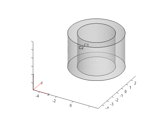
Create and plot a 3-D geometry consisting of three nested cuboids of the same height.

gm = multicuboid([2 3 5],[4 6 10],3);
pdegplot(gm,CellLabels="on",FaceAlpha=0.3)

Figure contains an axes object. The axes object contains 6 objects of type quiver, text, patch, line.

Create an femodel object for solving a static structural problem and assign the geometry to the model.

model = femodel(AnalysisType="structuralStatic", ...
                Geometry=gm);
model.Geometry
ans = 
  fegeometry with properties:

       NumCells: 3
       NumFaces: 18
       NumEdges: 36
    NumVertices: 24
       Vertices: [24x3 double]
           Mesh: []

Create an fegeometry object from an STL file representing a forearm link, and use it for a finite element analysis with an femodel object.

Create an femodel object for solving a static structural problem, and assign the geometry to the model.

model = femodel(AnalysisType="structuralStatic", ...
                Geometry="ForearmLink.stl");
model.Geometry
ans = 
  fegeometry with properties:

       NumCells: 1
       NumFaces: 147
       NumEdges: 329
    NumVertices: 213
       Vertices: [213x3 double]
           Mesh: []

Plot the geometry.

pdegplot(model,FaceAlpha=0.3)

Figure contains an axes object. The axes object contains 6 objects of type quiver, text, patch, line.

Create an fegeometry object from a function handle.

gm = fegeometry(@cardg)
gm = 
  fegeometry with properties:

       NumCells: 0
       NumFaces: 1
       NumEdges: 4
    NumVertices: 4
       Vertices: [4x2 double]
           Mesh: []

Plot the geometry with the edge labels.

pdegplot(gm,EdgeLabels="on");

Figure contains an axes object. The axes object contains 5 objects of type line, text.

Create an fegeometry object from a geometry description matrix.

g = [3 4 0 1 1 0 0 0 1.0 1.0];
sf = 'S1'; 
ns = 'S1';
gm = fegeometry(decsg(g',sf,ns'))
gm = 
  fegeometry with properties:

       NumCells: 0
       NumFaces: 1
       NumEdges: 4
    NumVertices: 4
       Vertices: [4x2 double]
           Mesh: []

Plot the geometry with the edge labels.

pdegplot(gm,EdgeLabels="on");
xlim([-0.1 1.1])
ylim([-0.1 1.1])

Figure contains an axes object. The axes object contains 5 objects of type line, text.

Since R2023b

Create an fegeometry object from a 2-D triangulation object.

Define the points in a 2-D triangulation.

P = [2.5 8.0;
     6.5 8.0;
     2.5 5.0;
     6.5 5.0;
     1.0 6.5;
     8.0 6.5];

Define the triangulation connectivity list.

T = [5 3 1;
     3 2 1;
     3 4 2;
     4 6 2];

Create the triangulation representation.

TR = triangulation(T,P)
TR = 
  triangulation with properties:

              Points: [6x2 double]
    ConnectivityList: [4x3 double]

Create an fegeometry object from the triangulation object TR.

gm = fegeometry(TR)
gm = 
  fegeometry with properties:

       NumCells: 0
       NumFaces: 1
       NumEdges: 6
    NumVertices: 6
       Vertices: [6x3 double]
           Mesh: [1x1 FEMesh]

The created geometry includes a linear mesh.

gm.Mesh
ans = 
  FEMesh with properties:

             Nodes: [2x6 double]
          Elements: [3x4 double]
    MaxElementSize: 5
    MinElementSize: 2.1213
     MeshGradation: []
    GeometricOrder: 'linear'

To create a more accurate quadratic mesh, use generateMesh.

gm = generateMesh(gm);
gm.Mesh
ans = 
  FEMesh with properties:

             Nodes: [2x871 double]
          Elements: [6x408 double]
    MaxElementSize: 0.3046
    MinElementSize: 0.1523
     MeshGradation: 1.5000
    GeometricOrder: 'quadratic'

Since R2024b

Create a spherical geometry from a mesh represented by an FEMesh object and from a mesh represented by nodes and elements.

First, create and plot a mesh.

model = createpde;
model.Geometry = multisphere(10);
msh = generateMesh(model);
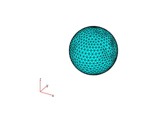
pdemesh(msh)

Figure contains an axes object. The hidden axes object contains 5 objects of type quiver, text, patch.

Create an fegeometry object representing a sphere by using the FEMesh object msh.

g1 = fegeometry(msh)
g1 = 
  fegeometry with properties:

       NumCells: 1
       NumFaces: 1
       NumEdges: 0
    NumVertices: 0
       Vertices: []
           Mesh: [1x1 FEMesh]

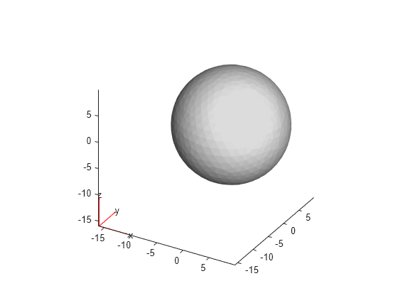
Plot the resulting geometry.

pdegplot(g1)

Figure contains an axes object. The axes object contains 5 objects of type quiver, text, patch.

Create an fegeometry object representing the same sphere by using the mesh nodes and elements as input arguments. Transpose the arrays representing the nodes and elements.

g2 = fegeometry(msh.Nodes',msh.Elements')
g2 = 
  fegeometry with properties:

       NumCells: 1
       NumFaces: 1
       NumEdges: 0
    NumVertices: 0
       Vertices: []
           Mesh: [1x1 FEMesh]

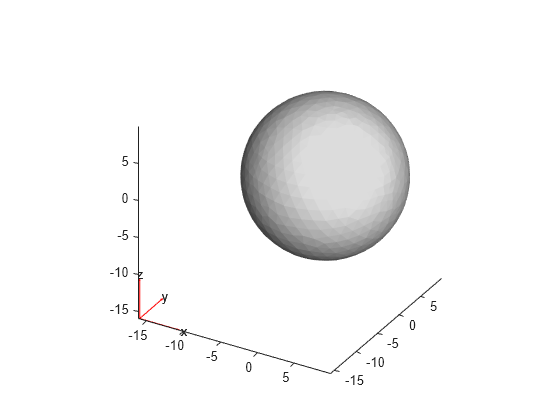
Plot the resulting geometry.

pdegplot(g2)

Figure contains an axes object. The axes object contains 10 objects of type quiver, text, patch.

Create a 2-D multidomain geometry from a planar mesh.

The MultidomainMesh2D file, which is included in Partial Differential Equation Toolbox™, contains a 2-D mesh. Load information about nodes, elements, and element-to-domain correspondence into your workspace.

load MultidomainMesh2D

Create a geometry from the mesh nodes and elements.

gm = fegeometry(nodes',elements',ElementIdToRegionId);

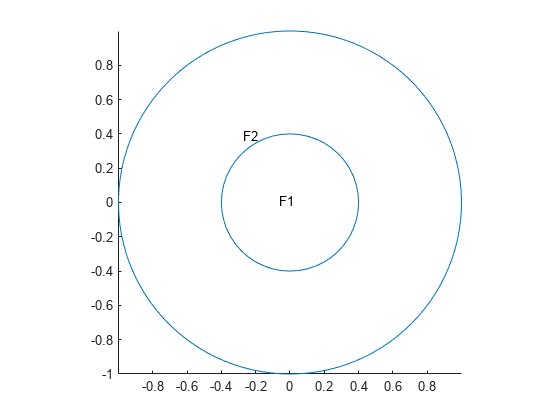
Plot the geometry with the face labels.

pdegplot(gm,FaceLabels="on")

Figure contains an axes object. The axes object contains an object of type line.

Since R2024b

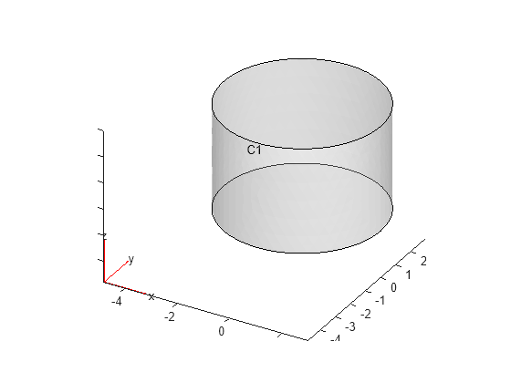
Create two geometries from a mesh, one with two cells and another with one cell.

The TwoCellMesh file contains a 3-D mesh specified by an FEMesh object and a vector specifying element-to-domain correspondence. Each vector element is a cell ID for an element of the mesh. Load this data into your workspace.

load TwoCellMesh;

Create a geometry from the mesh.

gm2cells = fegeometry(msh);

Plot the geometry with the cell labels.

pdegplot(gm2cells,CellLabels="on",FaceAlpha=0.3)

Figure contains an axes object. The axes object contains 6 objects of type quiver, text, patch, line.

Now, modify vector ElementIDToRegionID, which specifies the element-to-domain correspondence, so that all elements of the mesh belong to cell 1.

ElementIDToRegionID(:) = 1;

Create a geometry from the mesh. The resulting geometry has one cell.

gm1cell = fegeometry(msh,ElementIDToRegionID);

Plot the geometry with the cell label.

pdegplot(gm1cell,CellLabels="on",FaceAlpha=0.3)

Figure contains an axes object. The axes object contains 6 objects of type quiver, text, patch, line.

Since R2024a

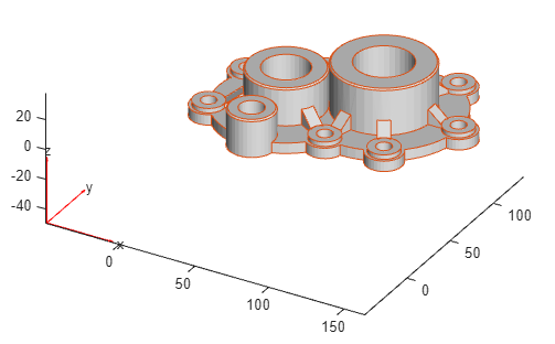
Check for self-intersections while importing the geometry of a cover.

Create an fegeometry object from an STL file and plot the geometry.

gm = fegeometry("Cover.stl");
pdegplot(gm)

Geometry of a head gasket cover of an engine block

Create an femodel object for solving a static structural problem, and assign the geometry to the model.

model = femodel(AnalysisType="structuralStatic", ...
                Geometry=gm);

Generate a mesh and assign the result to the model to update the mesh stored in the Geometry property of the model. The mesh generator issues a warning about poor quality of some of the mesh elements.

model = generateMesh(model);
Warning: Found elements with poor shape quality.
(Type "warning off pde:pdeMeshGenerator:ElementQualityWarn" to suppress this warning.) 
> In pde.EquationModel/generateMesh (line 104)
In fegeometry/generateMesh (line 220)
In femodel/generateMesh (line 344)

Rotate the geometry plot to check for any problematic areas. By looking at the top of the geometry, you can see that three of the cylinders might be in contact with each other or intersecting each other.

figure
pdegplot(gm)
view([30 90])

View of the geometry from Z-axis showing that three cylinders are very close to each other and might be intersecting each other

Use the AllowSelfIntersections argument to check for self-intersections while importing a geometry. If you set this argument to false, fegeometry does not allow the import if a geometry has self-intersections.

gm = fegeometry("Cover.stl",AllowSelfIntersections=false)
Unable to import a self-intersecting geometry.

Tips

  • For 3-D geometries symmetrical around an axis of rotation, you can speed up computations by simplifying a 3-D geometry to a 2-D geometry and setting the PlanarType property of femodel to "axisymmetric". The axis of rotation is the vertical axis, x = 0. The x–axis represents the radial component, and the y–axis represents the axial component.

Version History

Introduced in R2023a

expand all