directivity
Compute array directivity
Description
D = directivity(array,FREQ,ANGLE)array,
at frequencies specified by FREQ and in angles of direction specified by
ANGLE.
Note
The directivity object functions for arrays and elements differ. The
PropagationSpeed Name-Value pair argument does not appear in the element
version but does appear in the array version.
The integration used when computing array directivity has a minimum sampling grid of 0.1 degrees. If an array pattern has a beamwidth smaller than this, the directivity value will be inaccurate.
directivity(___, plots the
array pattern with additional options specified by one or more Name=Value)Name=Value
pair arguments.
Examples
Compute the directivities of two different uniform linear arrays (ULA). One array consists of isotropic antenna elements and the second array consists of cosine antenna elements. In addition, compute the directivity when the first array is steered in a specified direction. For each case, calculate the directivities for a set of seven different azimuth directions all at zero degrees elevation. Set the frequency to 300 MHz.
Array of Isotropic Antenna Elements
First, create a 10-element ULA of isotropic antenna elements spaced 1/2-wavelength apart.
c = physconst("LightSpeed");
fc = 300e6;
lambda = c/fc;
ang = [-30,-20,-10,0,10,20,30; 0,0,0,0,0,0,0];
myAnt1 = phased.IsotropicAntennaElement;
myArray1 = phased.ULA(10,lambda/2,Element=myAnt1);
Compute the directivity.
d = directivity(myArray1,fc,ang,PropagationSpeed=c)
d = 7×1

   -6.9897
   -6.2294
   -6.5187
   10.0000
   -6.5187
   -6.2294
   -6.9897
Array of Cosine Antenna Elements
Next, create a 10-element ULA of cosine antenna elements spaced 1/2-wavelength apart.
myAnt2 = phased.CosineAntennaElement(CosinePower=[1.8,1.8]);
myArray2 = phased.ULA(10,lambda/2,Element=myAnt2);
Compute the directivity.
d = directivity(myArray2,fc,ang,PropagationSpeed=c)
d = 7×1

   -1.9838
    0.0529
    0.4968
   17.2548
    0.4968
    0.0529
   -1.9838
The directivity of the cosine ULA is greater than the directivity of the isotropic ULA because of the larger directivity of the cosine antenna element.
Steered Array of Isotropic Antenna Elements
Finally, steer the isotropic antenna array to 30 degrees in azimuth and compute the directivity.
w = steervec(getElementPosition(myArray1)/lambda,[30;0]);
d = directivity(myArray1,fc,ang,PropagationSpeed=c, ...
    Weights=w)
d = 7×1
-297.2705
-13.9783
-9.5713
-6.9897
-4.5787
-2.0537
10.0000
The directivity is greatest in the steered direction.
Show that the pattern object function gives the same result as the directivity function. Create a 5x7-element URA operating at 1 GHz. Assume the elements are spaced one-half wavelength apart.
First, set up the URA.
elem = phased.CosineAntennaElement( ...
    FrequencyRange=[50e6,1000e6]);
fc = 500e6;
c = physconst("LightSpeed");
lam = c/fc;
array = phased.URA(Element=elem,Size=[5,7], ...
    ElementSpacing=0.5*lam);
Use the pattern object function to display the array directivity for azimuth angles from to , all at elevation.
[pat,az_ang,el_ang] = pattern(array,fc, ...
    [-45:45],45, CoordinateSystem="polar", ...
    Type="directivity",PropagationSpeed=c);
plot(az_ang,pat)
hold on
Using the directivity object function, display the directivity at several discrete angles.
ang = [-30,-20,-10,0,10,20,30; ...
    45,45,45,45,45,45,45];
d = directivity(array,fc,ang, ...
    PropagationSpeed=c);
plot(ang(1,:),d,'*')
legend("pattern function","directivity function", ...
    "location","southwest")
hold off
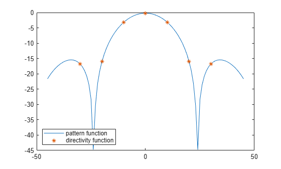
The two computations coincide.
Input Arguments
Name-Value Arguments
Output Arguments
More About
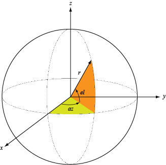
Define the azimuth and elevation conventions used in the toolbox.
The azimuth angle of a vector is the angle between the x-axis and its orthogonal projection onto the xy-plane. The angle is positive when going from the x-axis toward the y-axis. Azimuth angles lie between –180° and 180° degrees, inclusive. The elevation angle is the angle between the vector and its orthogonal projection onto the xy-plane. The angle is positive when going toward the positive z-axis from the xy-plane. Elevation angles lie between –90° and 90° degrees, inclusive.
Extended Capabilities
Version History
Introduced in R2021a