Main Content

step

System object: phased.FreeSpace
Namespace: phased

Propagate signal from one location to another

Syntax

Y = step(SFS,F,origin_pos,dest_pos,origin_vel,dest_vel)

Description

Note

Starting in R2016b, instead of using the step method to perform the operation defined by the System object™, you can call the object with arguments, as if it were a function. For example, y = step(obj,x) and y = obj(x) perform equivalent operations.

Y = step(SFS,F,origin_pos,dest_pos,origin_vel,dest_vel) returns the resulting signal Y when the narrowband signal F propagates in free space from the position or positions specified in origin_pos to the position or positions specified in dest_pos. For non-polarized signals, either the origin_pos or dest_pos arguments can specify more than one point. Using both arguments to specify multiple points is not allowed. The velocity of the signal origin is specified in origin_vel and the velocity of the signal destination is specified in dest_vel. The dimensions of origin_vel and dest_vel must agree with the dimensions of origin_pos and dest_pos, respectively.

Note

The object performs an initialization the first time the object is executed. This initialization locks nontunable properties and input specifications, such as dimensions, complexity, and data type of the input data. If you change a nontunable property or an input specification, the System object issues an error. To change nontunable properties or inputs, you must first call the release method to unlock the object.

Input Arguments

expand all

Free-space propagator, specified as a System object.

Narrowband signal, specified as an M-element complex-valued column vector, M-by-N complex-valued matrix or structure containing complex-valued fields.

Polarization Signal structure
Not enabled

The signal X can be a complex-valued 1-by-M column vector or complex-valued M-by-N matrix. The quantity M is the number of sample values of the signal and N is the number of signals to propagate. When you specify N signals, you need to specify N signal origins or N signal destinations.

The size of the first dimension of the input matrix can vary to simulate a changing signal length. A size change can occur, for example, in the case of a pulse waveform with variable pulse repetition frequency.

Enabled

The signal X is a MATLAB® struct containing three matrix fields:X.X, X.Y, and X.Z representing the x, y, and z components of the polarized signals.

The size of the first dimension of the matrix fields within the struct can vary to simulate a changing signal length such as a pulse waveform with variable pulse repetition frequency.

Origin of the signal or signals, specified as a 3-by-1 real-valued column vector or 3-by-N real-valued matrix. Position units are meters. The quantity N is the number of signals arriving from N signal origins and matches the dimension specified in the signal X. If origin_pos is a column vector, it takes the form [x; y; z]. If origin_pos is a matrix, each column specifies a different signal origin and has the form [x; y; z]. origin_pos and dest_pos cannot both be specified as matrices — at least one must be a 3-by-1 column vector.

Destination of the signal or signals, specified as a 3-by-1 column vector or 3-by-N matrix. Position units are meters. The quantity N is the number of signals arriving at N signal destinations and matches the dimension specified in the signal X. If dest_pos is a column vector, it takes the form [x; y; z]. If dest_pos is a matrix, each column specifies a different destination and has the form [x; y; z]. dest_pos and origin_pos cannot both be specified as matrices — at least one must be a 3-by-1 column vector.

Velocity of signal origin, specified as a 3-by-1 column vector or 3-by-N matrix. Velocity units are meters/second. The dimensions of origin_vel must match the dimensions of origin_pos. If origin_vel is a column vector, it takes the form [Vx; Vy; Vz]. If origin_vel is a 3–by-N matrix, each column specifies a different origin velocity and has the form [Vx; Vy; Vz].

Velocity of signal destinations, specified as a 3-by-1 column vector or 3–by-N matrix. Velocity units are meters/second. The dimensions of dest_vel must match the dimensions of dest_pos. If dest_vel is a column vector, it takes the form [Vx; Vy; Vz]. If dest_vel is a 3–by-N matrix, each column specifies a different destination velocity and has the form [Vx; Vy; Vz].

Output Arguments

Y

Propagated signal, returned as a M-element complex-valued column vector, M-by-N complex-valued matrix or MATLAB structure containing complex-valued fields.

If X is a column vector or matrix, Y is also a column vector or matrix with the same dimensions.

If X is a struct, Y is also a struct with the same fields. Each field in Y contains the resulting signal of the corresponding field in X.

The output Y contains signal samples arriving at the signal destination within the current time frame. The current time frame is defined as the time spanned by the current input. Whenever it takes longer than the current time frame for the signal to propagate from the origin to the destination, the output contains no contribution from the input of the current time frame.

Examples

expand all

Calculate the amplitude of a signal propagating in free space from a radar at (40000,0,0) to a target at (300,200,50). Assume both the radar and the target are stationary. The sample rate is 8000 Hz while the operating frequency of the radar is 300 MHz. Transmit five samples of a unit amplitude signal. The signal propagation speed takes the default value of the speed of light. Examine the amplitude of the signal at the target.

fs = 8e3;
fop = 3e8;
freesp = phased.FreeSpace(SampleRate=fs, ...
    OperatingFrequency=fop);
pos1 = [40000;0;0];
pos2 = [300;200;50];
vel1 = [0;0;0];
vel2 = [0;0;0];

Create the transmitted signal.

x = ones(5,1);

Find the received signal at the target.

y = freesp(x,pos1,pos2,vel1,vel2);
disp(y)
   1.0e-05 *

   0.0000 + 0.0000i
   0.1870 - 0.0229i
   0.1988 - 0.0243i
   0.1988 - 0.0243i
   0.1988 - 0.0243i

The first sample is zero because the signal has not yet reached the target.

Manually compute the loss using the formula

L=(4πR/λ)2

R = sqrt((pos1-pos2)'*(pos1-pos2));
lambda = physconst('Lightspeed')/fop;
L = (4*pi*R/lambda)^2
L = 
2.4924e+11

Because the transmitted amplitude is unity, the magnitude-squared value of the signal at the target for the third sample equals the inverse of the loss.

disp(1/abs(y(3))^2)
   2.4924e+11

Calculate the result of propagating a signal in free space from a radar at (1000,0,0) to a target at (300,200,50). Assume the radar moves at 10 m/s along the x-axis, while the target moves at 15 m/s along the y-axis. The sample rate is 8000 Hz while the operating frequency of the radar is 300 MHz. The signal propagation speed takes the default value of the speed of light. Transmit five samples of a unit amplitude signal and examine the amplitude of the signal at the target.

fs = 8000;
fop = 3e8;
freesp = phased.FreeSpace(SampleRate=fs, ...
    OperatingFrequency=fop);
pos1 = [1000;0;0];
pos2 = [300;200;50];
vel1 = [10;0;0];
vel2 = [0;15;0];
y = freesp(ones(5,1),pos1,pos2,vel1,vel2);
disp(y)
   1.0e-03 *

   0.0126 - 0.1061i
   0.0117 - 0.1083i
   0.0105 - 0.1085i
   0.0094 - 0.1086i
   0.0082 - 0.1087i

Because the transmitted amplitude is unity, the square of the signal at the target equals the inverse of the loss.

disp(1/abs(y(2))^2)
   8.4206e+07

Create a uniform linear array (ULA) consisting of four short-dipole antenna elements that support polarization. Set the orientation of each dipole to the z-direction. Set the operating frequency to 300 MHz and the element spacing of the array to 0.4 meters. While the antenna element supports polarization, you must explicitly enable polarization in the Radiator System object™.

Create the short-dipole antenna element, ULA array, and radiator System objects. Set the CombineRadiatedSignals property to true to coherently combine the radiated signals from all antennas and the Polarization property to 'Combined' to process polarized waves.

freq = 300e6;
nsensors = 4;
c = physconst('LightSpeed');
antenna = phased.ShortDipoleAntennaElement('FrequencyRange',[100e6 900e6],...
    'AxisDirection','Z');
array = phased.ULA('Element',antenna,...
    'NumElements',nsensors,...
    'ElementSpacing',0.4);
radiator = phased.Radiator('Sensor',array,...
    'PropagationSpeed',c,...
    'OperatingFrequency',freq,...
    'CombineRadiatedSignals',true,...
    'Polarization','Combined',...
    'WeightsInputPort',true);

Create a signal to be radiated. In this case, the signal consists of one cycle of a 4 kHz sinusoid. Set the signal amplitude to unity. Set the sampling frequency to 8 kHz. Choose radiating angles of 0 degrees azimuth and 20 degrees elevation. For polarization, you must set a local axes - in this case chosen to coincide with the global axes. Set uniform weights on the elements of the array.

fsig = 4000;
fs = 8000;
A = 1;
t = [0:0.01:2]/fs;
signal = A*sin(2*pi*fsig*t');
radiatingAngles = [0;20];
laxes = ones(3,3);
y = radiator(signal,radiatingAngles,laxes,[1,1,1,1].');
disp(y)
    X: [201x1 double]
    Y: [201x1 double]
    Z: [201x1 double]

The radiated signal is a struct containing the polarized field.

Use a FreeSpace System object to propagate the field from the origin to the destination.

propagator = phased.FreeSpace('PropagationSpeed',c,...
    'OperatingFrequency',freq,...
    'TwoWayPropagation',false,...
    'SampleRate',fs);

Set the signal origin, signal origin velocity, signal destination, and signal destination velocity.

origin_pos = [0; 0; 0];
dest_pos = [500; 200; 50];
origin_vel = [10; 0; 0];
dest_vel = [0; 15; 0];

Call the FreeSpace object to propagate the signals.

yprop = propagator(y,origin_pos,dest_pos,...
    origin_vel,dest_vel);

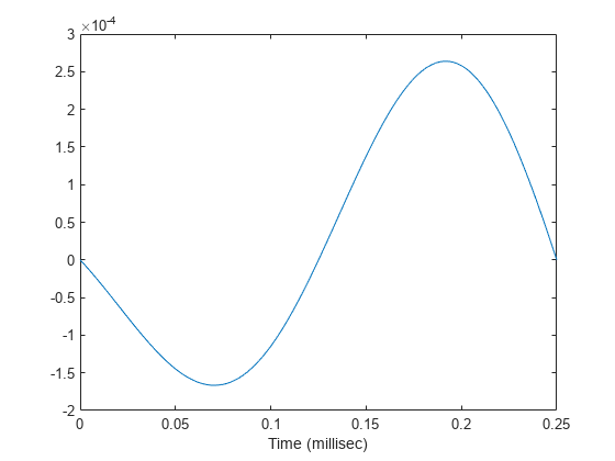
Plot the x-component of the propagated signals.

figure
plot(1000*t,real(yprop.X))
xlabel('Time (millisec)')

Figure contains an axes object. The axes object with xlabel Time (millisec) contains an object of type line.

Create a FreeSpace System object™ to propagate a signal from one point to multiple points in space. Start by defining a signal origin and three destination points, all at different ranges.

Compute the propagation direction angles from the source to the destination locations. The source and destination are stationary.

pos1 = [0,0,0]';
vel1 = [0,0,0]';
pos2 = [[700;700;100],[1400;1400;200],2*[2100;2100;400]];
vel2 = zeros(size(pos2));
[rngs,radiatingAngles] = rangeangle(pos2,pos1);

Create the cosine antenna element, ULA array, and Radiator System objects.

fs = 8000;
freq = 300e6;
nsensors = 4;
sAnt = phased.CosineAntennaElement;
sArray = phased.ULA('Element',sAnt,'NumElements',nsensors);
sRad = phased.Radiator('Sensor',sArray,...
    'OperatingFrequency',freq,...
    'CombineRadiatedSignals',true,'WeightsInputPort',true);

Create a signal to be one cycle of a sinusoid of amplitude one and having a frequency of 4 kHz.

fsig = 4000;
t = [0:0.01:2]'/fs;
signal = sin(2*pi*fsig*t);

Radiate the signals in the destination directions. Apply a uniform weighting to the array.

y = step(sRad,signal,radiatingAngles,[1,1,1,1].');

Propagate the signals to the destination points.

sFSp = phased.FreeSpace('OperatingFrequency',freq,'SampleRate',fs);
yprop = step(sFSp,y,pos1,pos2,vel1,vel2);

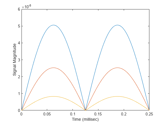
Plot the propagated signal magnitudes for each range.

figure
plot(1000*t,abs(yprop(:,1)),1000*t,abs(yprop(:,2)),1000*t,abs(yprop(:,3)))
ylabel('Signal Magnitude')
xlabel('Time (millisec)')

Figure contains an axes object. The axes object with xlabel Time (millisec), ylabel Signal Magnitude contains 3 objects of type line.

Algorithms

When the origin and destination are stationary relative to each other, you can write the output signal of a free-space channel as Y(t) = x(t-τ)/Lfsp. The quantity τ is the signal delay and Lfsp is the free-space path loss. The delay τ is given by R/c, where R is the propagation distance and c is the propagation speed. The free-space path loss is given by

Lfsp=(4πR)2λ2,

where λ is the signal wavelength.

This formula assumes that the target is in the far field of the transmitting element or array. In the near field, the free-space path loss formula is not valid and can result in a loss smaller than one, equivalent to a signal gain. Therefore, the loss is set to unity for range values, R ≤ λ/4π.

When the origin and destination have relative motion, the processing also introduces a Doppler frequency shift. The frequency shift is v/λ for one-way propagation and 2v/λ for two-way propagation. The quantity v is the relative speed of the destination with respect to the origin.

For further details, see [2].

References

[1] Proakis, J. Digital Communications. New York: McGraw-Hill, 2001.

[2] Skolnik, M. Introduction to Radar Systems, 3rd Ed. New York: McGraw-Hill, 2001.

See Also

(Radar Toolbox) |