Build Manipulator Robot Using Kinematic DH Parameters
Use the Denavit-Hartenberg (DH) parameters of the Puma560® manipulator robot to incrementally build a rigid body tree robot model. Specify the relative DH parameters for each joint as you attach them. Visualize the robot frames, and interact with the final model.
The DH parameters define the geometry of how each rigid body attaches to its parent via a joint. The parameters follow a four transformation convention:
— Length of the common normal line between the two z-axes, which is perpendicular to both axes
— Angle of rotation for the common normal
— Offset along the z-axis in the normal direction, from parent to child
— Angle of rotation for the x-axis along the previous z-axis
Specify the parameters for the Puma560 robot [1] as a matrix.
dhparams = [0   	pi/2	0   	0;
            0.4318	0       0       0
            0.0203	-pi/2	0.15005	0;
            0   	pi/2	0.4318	0;
            0       -pi/2	0   	0;
            0       0       0       0];
Create a rigid body tree object.
robot = rigidBodyTree;
Create a cell array for the rigid body object, and another for the joint objects. Iterate through the DH parameters performing this process:
Create a
rigidBodyobject with a unique name.Create and name a revolute
rigidBodyJointobject.Use
setFixedTransformto specify the body-to-body transformation of the joint using DH parameters. The function ignores the final element of the DH parameters,theta, because the angle of the body is dependent on the joint position.Use
addBodyto attach the body to the rigid body tree.
bodies = cell(6,1);
joints = cell(6,1);
for i = 1:6
    bodies{i} = rigidBody(['body' num2str(i)]);
    joints{i} = rigidBodyJoint(['jnt' num2str(i)],"revolute");
    setFixedTransform(joints{i},dhparams(i,:),"dh");
    bodies{i}.Joint = joints{i};
    if i == 1 % Add first body to base
        addBody(robot,bodies{i},"base")
    else % Add current body to previous body by name
        addBody(robot,bodies{i},bodies{i-1}.Name)
    end
end
Verify that your robot has been built properly by using the showdetails or show function. The showdetails function lists all the bodies of the robot in the MATLAB® command window. The show function displays the robot with a specified configuration (home by default).
showdetails(robot)
--------------------
Robot: (6 bodies)

 Idx    Body Name   Joint Name   Joint Type    Parent Name(Idx)   Children Name(s)
 ---    ---------   ----------   ----------    ----------------   ----------------
   1        body1         jnt1     revolute             base(0)   body2(2)
   2        body2         jnt2     revolute            body1(1)   body3(3)
   3        body3         jnt3     revolute            body2(2)   body4(4)
   4        body4         jnt4     revolute            body3(3)   body5(5)
   5        body5         jnt5     revolute            body4(4)   body6(6)
   6        body6         jnt6     revolute            body5(5)
--------------------
figure(Name="PUMA Robot Model")
show(robot);
Interact with Robot Model
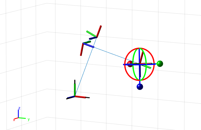
Visualize the robot model to confirm its dimensions by using the interactiveRigidBodyTree object.
figure(Name="Interactive GUI")
gui = interactiveRigidBodyTree(robot,MarkerScaleFactor=0.5);
Click and drag the marker in the interactive GUI to reposition the end effector. The GUI uses inverse kinematics to solve for the joint positions that achieve the best possible match to the specified end-effector position. Right-click a specific body frame to set it as the target marker body, or to change the control method for setting specific joint positions.
Next Steps
Now that you have built your model in MATLAB®, these are some possible next steps.
Perform Inverse Kinematics to get joint configurations based on desired end-effector positions. Specify robot constraints in addition to those of the model parameters, including aiming constraints, Cartesian bounds, and pose targets.
Trajectory Generation, based on waypoints and other parameters, with trapezoidal velocity profiles, B-splines, or polynomial trajectories.
Perform Manipulator Planning utilizing your robot models and a rapidly-exploring random tree (RRT) path planner.
Use Collision Detection with obstacles in your environment to ensure safe and effective motion for your robot.
References
[1] Corke, P. I., and B. Armstrong-Helouvry. “A Search for Consensus Among Model Parameters Reported for the PUMA 560 Robot.” Proceedings of the 1994 IEEE International Conference on Robotics and Automation, 1608–13. San Diego, CA, USA: IEEE Computer Soc. Press, 1994. https://doi.org/10.1109/ROBOT.1994.351360.