Configure Gazebo and Simulink for Co-simulation of a Manipulator Robot
Set up a UR10 robot model to perform co-simulation between Gazebo and Simulink™. Co-simulation with Gazebo enables you to connect directly from Simulink to Gazebo and control simulation pacing using the Simulink model.
For an introduction to Gazebo co-simulation and getting connected for the first time, see Perform Co-Simulation Between Simulink and Gazebo. This example uses the virtual machine and plug-in provided in that example, but also tells you how to configure your own model and system. The robot arm used in this example is a 6-DoF robot, the Universal Robots UR10.
Create Robot Representations for MATLAB and Gazebo
First, add the manipulator to a Gazebo .world file. In this example, a world file is provided (Ur10BasicWithPlugin.world) that was created from the provided robot models in the loadrobot function. If your goal is just to interface with the Gazebo simulation, a world file is sufficient. To see how to control a model using just the world file, see Control Differential Drive Robot in Gazebo with Simulink. However, the goal of this example is to control the robot using model-based tools in MATLAB® and Simulink. Therefore, you should also define a rigid body tree robot model for your manipulator in MATLAB. There are several ways to obtain these representations together:
Provided Robot Models: Obtain the rigid body tree from the
loadrobotfunction, then create a model for Gazebo using the source repository.Custom URDF Models: Import a URDF file as a rigid body tree object via the
importrobotfunction. Manually modify the URDF file to make it compatible with the Gazebo SDF model format. Save the model to a new or existing .world file. If you only have a Gazebo .world file, consider modifying a similar manipulator or building the robot from scratch, using queries of the Gazebo world.
Load Robot Model
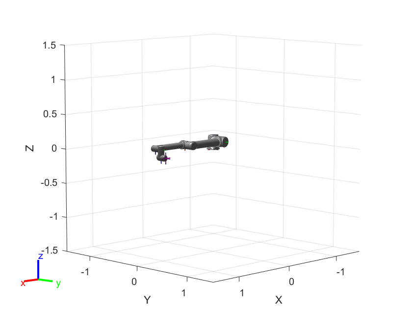
To get started, load and show the robot in MATLAB.
[robot,info] = loadrobot('universalUR10','Gravity',[0 0 -9.81]);
show(robot);
Create Gazebo World from Robot Model
The Ur10BasicWithPlugin.world world file attached to this example is also provided in the virtual machine from the Perform Co-Simulation Between Simulink and Gazebo example. If you are using the virtual machine provided in that example, skip directly to Open World in Gazebo.
The world file contains a UR10 robot with the base joint fixed to the ground and a red box to manipulator. The world was created using the source repository provided in the info output:
info.Source
ans =
"https://github.com/ros-industrial/universal_robot/tree/1.2.1"
The following steps were used to create the Ur10BasicWithPlugin.world file:
Open the repository linked in
info.Sourceand install per the instructions in thereadmefile. Make sure the tags match so that the robot's numerical data matches that used in the equivalent rigid body tree object. If using the provided virtual machine, make sure to allot at least 4 GB RAM and 4 cores to avoid compilation errors. On the provided Virtual Machine, some of the tools in the associated ROS package have been disabled to avoid dependency issues during installation:
%# Ignore the ur_kinematics package
touch universal_robot/ur_kinematics/CATKIN_IGNORE
The repository installs a package to open a world using the
roslaunchcommand:
roslaunch ur_gazebo ur10.launch
Save the newly created world to a .world file. You may also save the model to an SDF file and add it to an existing world, manually or via the Gazebo GUI.
In the world file source code, fix the robot to the ground plane by manually adding a fixed joint to the robot model.
<!-- Add a custom fixed joint that fixes the robot to the world-->
<joint name="world_to_robot" type="fixed">
   <parent>world</parent>
   <child>ur10::base_link</child>
</joint>
In the world file source code, add a red box object that can be moved around.
<!-- Add a red box -->
    <model name='redBox'>
      <link name='link'>
% See file for more
In the world file source code, attach the Gazebo plug-in by adding the following lines:
<!-- Include the Gazebo plugin to ensure connection to MATLAB/Simulink -->
<plugin name="GazeboPlugin" filename="lib/libGazeboCoSimPlugin.so">
    <portNumber>14581</portNumber>
</plugin>
The Ur10BasicWithPlugin.world world file attached to this example has additional comments to clarify the various elements. To learn more about robot elements in a Gazebo world, search the Gazebo documentation for the "Make A Simple Gripper" tutorial.
Set Up Gazebo with Robot Model and Plugin
To run this example, you must have access to a machine with Gazebo with the plugin for co-simulation installed and the provided world file. These steps are covered in Perform Co-Simulation Between Simulink and Gazebo. If you are using the virtual machine provided in that example, skip directly to Open World in Gazebo. Virtual machines downloaded prior to the R2021a release may need to be updated.
To execute this example, you must either be able to connect to a machine with Linux installed with an environment that has been configured accordingly:
Set up the Gazebo environment and add the plug-in. Follow the Install Gazebo Plugin Manually instructions in Perform Co-Simulation Between Simulink and Gazebo. This example assumes that the plug-in is located in the
home/user/src/GazeboPlugIndirectory.Add the provided world file to the directory
/home/user/worldsAccess the robot mesh files from the robot model. The mesh files are Collada (*.DAE files) that are required to visualize the robot.
loadrobot, so the repository linked ininfo.Sourcecontains all the associated information, including meshes.
disp(info.Source)
https://github.com/ros-industrial/universal_robot/tree/1.2.1
Execute the following commands on the Gazebo machine to clone the linked repository. The URL in the second command should match
info.Source.
cd /home/user/catkin_ws/src
git clone -b 1.2.1 https://github.com/ros-industrial/universal_robot/

%# (Optional) Ignore UR_Kinematic package to avoid dependency issue during build
touch universal_robot/ur_kinematics/CATKIN_IGNORE
Please note that it is not necessary to build the package for this example to work (this example just requires the associated mesh files), though doing so will not cause any issues either.
Check to ensure the robot mesh files are located at /home/user/catkin_ws/src/universal_robot/ur_description/.
Open World in Gazebo
Open the world by running these commands in the terminal of the Gazebo machine:
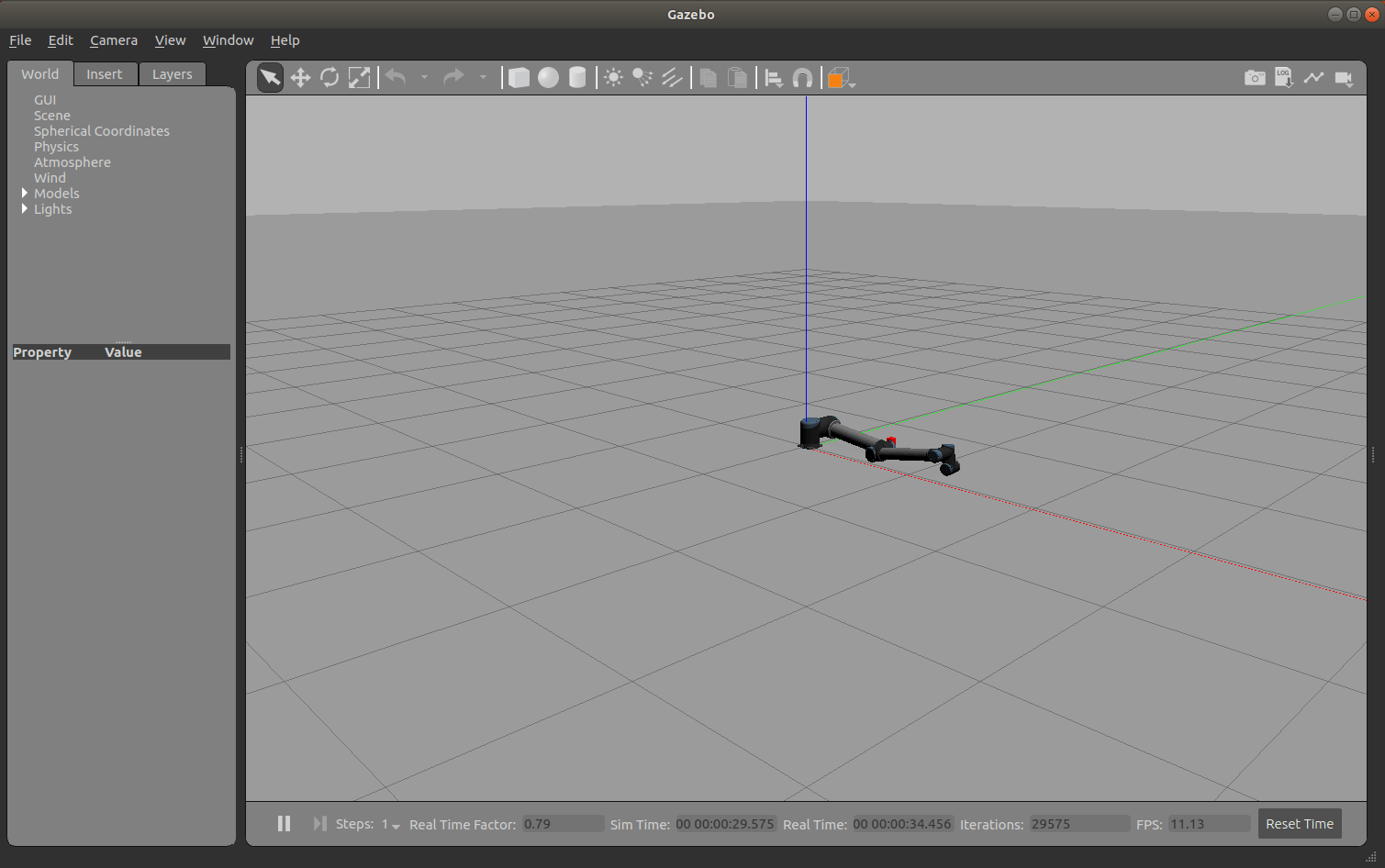
cd /home/user/src/GazeboPlugin/export
export SVGA_VGPU10=0
gazebo /home/user/worlds/Ur10BasicWithPlugin.world --verbose
Gazebo shows the robot and any other objects in the world.
If the Gazebo simulator fails to open, you may need to reinstall the plugin. See Install Gazebo Plugin Manually in Perform Co-Simulation Between Simulink and Gazebo.
Connect to Gazebo
Next, initialize the Gazebo connection to MATLAB and Simulink. Specify the IP address and a port number of 14581, which is the default port for the Gazebo plugin.
ipGazebo = '192.168.116.162'; % Replace this with the IP of the Gazebo machine
gzinit(ipGazebo,14581);
Inspect the Model
Verify that the model has the desired elements using the Gazebo MATLAB interface commands. Call the gzmodel function to return all the models in the current Gazebo world.
gzmodel('list')MODEL LIST: ground_plane ur10 redBox
List the links in the UR10 robot model.
gzlink("list","ur10")
MODEL:  ur10


LINKS:  base_link forearm_link shoulder_link upper_arm_link wrist_1_link wrist_2_link wrist_3_link
Control Robot Position in Simulink
Now that the Gazebo world is connected to MATLAB, you can perform co-simulation from Simulink to advance the simulation state in Gazebo.
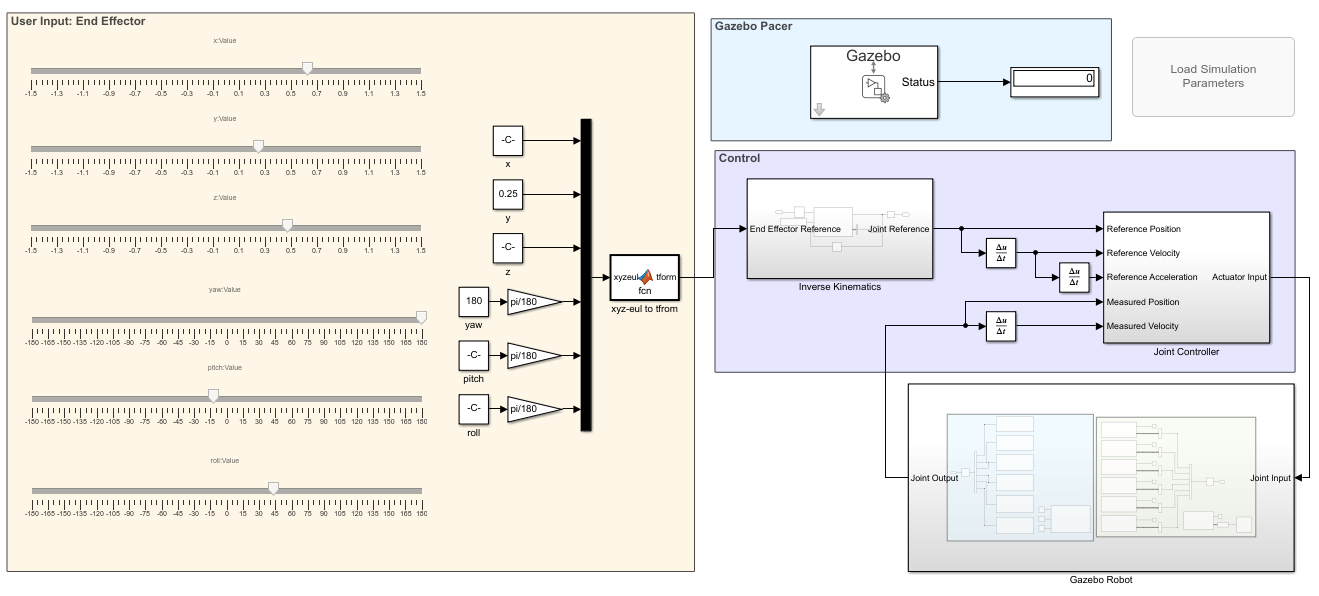
The gazeboCosimControl model controls the end-effector position of the manipulator using the sliders in the User Input: End Effector section. The Inverse Kinematics subsystem generates a joint configuration that achieves the desired position. Then, the Joint Controller subsystems generates torque forces for each joint to reach this position. Details about this model can be found in the Control Manipulator Robot with Co-Simulation in Simulink and Gazebo example.
The Gazebo Pacer block controls the stepping of Gazebo based on Simulink steps.
Open the model and initialize the model parameters for the trajectory, starting position, and bus objects for sending commands.
% Open the model
open_system('gazeboCosimControl');

% Initialize parameters
Ts = 0.01;
Ts_trajectory = 0.05;
q0 = [0 -70 140 0 0 0]' * pi/180;
load('custom_busobjects_basic');
Simulate the model for a few seconds.
sim('gazeboCosimControl','StopTime','5');
Use the sliders in the User Input: End Effector area on the left to control the position of the robot.
Now run the model directly using the green "run" arrow.
While the simulation is running, you may send MATLAB commands to update the world state. For example, move the red box to a new location.
% Move the box to a new position on the opposite side of the robot and 0.3 m off the ground
gzlink("set","redBox","link","Position",[0.5 -0.4 .3])
STATUS:  Succeed


MESSAGE:  Parameter set successfully.
Change the robot position by setting a joint position and see how the controller responds.
% Move the robot shoulder lift joint to pi/4
[status,message] = gzjoint('set','ur10','shoulder_lift_joint','Axis','0','Angle',-pi/4);
Since Gazebo is now being stepped by Simulink, pausing the Simulink model also pauses the Gazebo simulation.
Next Steps
To learn more about the gazeboCosimControl model for controlling the robot in simulation, see the Control Manipulator Robot with Co-Simulation in Simulink and Gazebo example.