Pick-and-Place Workflow Using RRT Planner and Stateflow for MATLAB
This example shows how to setup an end-to-end pick-and-place workflow for a robotic manipulator like the Kinova® Gen3.
The pick-and-place workflow implemented in this example can be adapted to different scenarios, planners, simulation platforms, and object detection options. The example shown here uses the rapidly-exploring random tree (RRT) algorithm for planning, and simulates the robot in MATLAB®. For other uses, see:
Overview
This example sorts detected objects onto shelves using a Kinova Gen3 manipulator. The example uses tools from two toolboxes:
Robotics System Toolbox™ is used to model, simulate, and visualize the manipulator, and plan collision-free paths for the manipulator to follow using RRT.
Stateflow® is used to schedule the high-level tasks in the example and step from task to task.
This example uses the RRT algorithm for path planning. For another example that goes into more details about the RRT planner, see Pick-and-Place Workflow Using RRT for Manipulators.
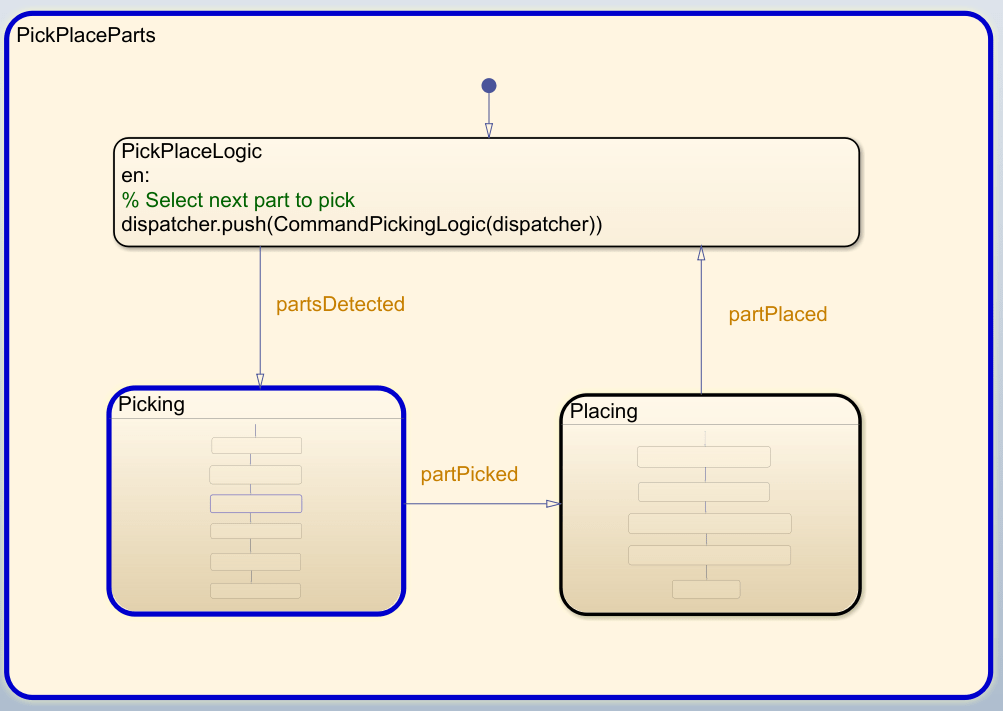
Stateflow Chart
This example uses a Stateflow chart to schedule tasks in the example. Open the chart to examine the contents and follow state transitions during chart execution.
edit exampleHelperFlowChartPickPlaceRRT.sfxThe chart dictates how the manipulator interacts with the objects, or parts. It consists of basic initialization steps, followed by two main sections:
Identify Parts and Determine Where to Place Them
Execute Pick-and-Place Workflow
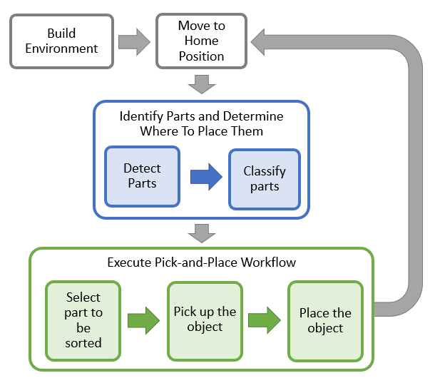
Initialize the Robot and Environment
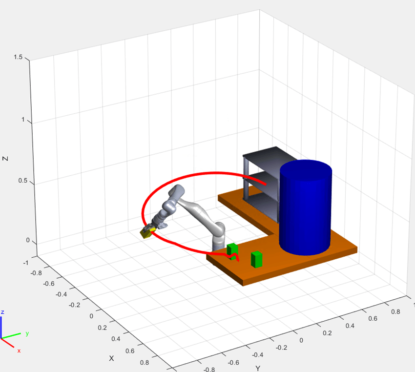
First, the chart creates an environment consisting of the Kinova Gen3 manipulator, three parts to be sorted, the shelves used for sorting, and a blue obstacle. Next, the robot moves to the home position.
Identify the Parts and Determine Where to Place Them
In the first step of the identification phase, the parts must be detected. The exampleCommandDetectParts function directly gives the object poses. Replace this class with your own object detection algorithm based on your sensors or objects.
Next, the parts must be classified. The exampleCommandClassifyParts function classifies the parts into two types to determine where to place them (top or bottom shelf). Again, you can replace this function with any method for classifying parts.
Execute Pick-and-Place Workflow
Once parts are identified and their destinations have been assigned, the manipulator must iterate through the parts and move them onto the appropriate tables.
Pick Up the Object
The picking phase moves the robot to the object, picks it up, and moves to a safe position, as shown in the following diagram:
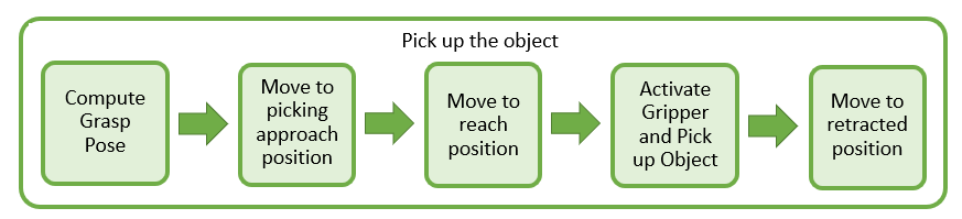
The exampleCommandComputeGraspPose function computes the grasp pose. The class computes a task-space grasping position for each part. Intermediate steps for approaching and reaching towards the part are also defined relative to the object.
This robot picks up objects using a simulated pneumatic gripper. When the gripper is activated, exampleCommandActivateGripper adds the collision mesh for the part onto the rigidBodyTree representation of the robot, by using the addCollision object function. Collision detection includes this object while it is attached. Then, the robot moves to a retracted position away from the other parts.
Place the Object
The robot then places the object on the appropriate shelf.
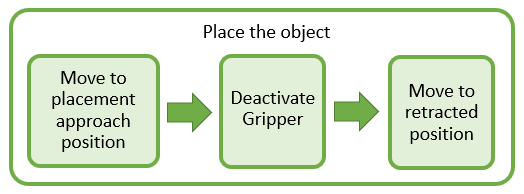
As with the picking workflow, the placement approach and retracted positions are computed relative to the known desired placement position. The gripper is deactivated using exampleCommandActivateGripper, which removes the part from the robot, using clearCollision. Every time a part of specific type is placed, the placing pose for this object type is updated so that next part of same type is placed next to the placed part.
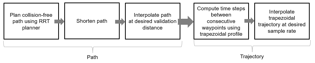
Moving the Manipulator to a Specified Pose
Most of the task execution consists of instructing the robot to move between different specified poses. The exampleHelperMoveToTaskConfig function defines an RRT planner using the manipulatorRRT object, which plans paths from an initial to a desired joint configuration by avoiding collisions with specified collision objects in the scene. The resulting path is first shortened and then interpolated at a desired validation distance. To generate a trajectory, the trapveltraj function is used to assign time steps to each of the interpolated waypoints following a trapezoidal profile. Finally, the waypoints with their associated times are interpolated to a desired sample rate (every 0.1 seconds). The generated trajectories ensure that the robot moves slowly at the start and the end of the motion when it is approaching or placing an object.
For another example that goes into more details about the RRT planner, see Pick-and-Place Workflow Using RRT for Manipulators.
For simpler trajectories where the paths are known to be obstacle-free, trajectories could be executed using trajectory generation tools and simulated using the manipulator motion models. See the Plan and Execute Task- and Joint-Space Trajectories Using Kinova Gen3 Manipulator example.
Task Scheduling in a Stateflow Chart
This example uses a Stateflow chart to direct the workflow in MATLAB®. For more info on creating state flow starts, see Create Stateflow Charts for Execution as MATLAB Objects (Stateflow).
The Stateflow chart directs task execution in MATLAB by using command functions. When the command finishes executing, it sends an input event to wake up the chart and proceed to the next step of the task execution, see Execute a Standalone Chart (Stateflow).
Run and Visualize the Simulation
This simulation uses a KINOVA Gen3 manipulator with a Robotiq gripper. Load the robot model from a .mat file as a rigidBodyTree object.
load('exampleHelperKINOVAGen3GripperCollRRT.mat'); Initialize the Pick and Place Coordinator
Set the initial robot configuration. Create the coordinator, which handles the robot control, by giving the robot model, initial configuration, and end-effector name.
currentRobotJConfig = homeConfiguration(robot);
coordinator = exampleHelperCoordinatorPickPlaceRRT(robot,currentRobotJConfig, "gripper");
Specify the home configuration and two poses for placing objects of two different types. The first pose corresponds to the middle shelf where all parts of type 1 are placed and the second pose corresponds to the top shelf where parts of type 2 are placed. The placing poses are updated in the Stateflow chart every time a new part is placed successfully. Parts of different type are identified by different colors in the visualization.
coordinator.HomeRobotTaskConfig = trvec2tform([0.4, 0, 0.5])*axang2tform([0 1 0 pi]);
coordinator.PlacingPose{1} = trvec2tform([[-0.15 0.52 0.46]])*axang2tform([1 0 0 -pi/2]);
coordinator.PlacingPose{2} = trvec2tform([[-0.15 0.52 0.63]])*axang2tform([1 0 0 -pi/2]);
Run and Visualize the Simulation
Connect the coordinator to the Stateflow Chart. Once started, the Stateflow chart is responsible for continuously going through the states of detecting objects, picking them up and placing them in the correct staging area.
coordinator.FlowChart = exampleHelperFlowChartPickPlaceRRT('coordinator', coordinator); Use a dialog to start the pick-and-place task execution. Click Yes in the dialog to begin the simulation.
answer = questdlg('Do you want to start the pick-and-place job now?', ...
         'Start job','Yes','No', 'No');

switch answer
    case 'Yes'
        % Trigger event to start Pick and Place in the Stateflow Chart
        coordinator.FlowChart.startPickPlace;
    case 'No'
        % End Pick and Place
        coordinator.FlowChart.endPickPlace;
        delete(coordinator.FlowChart);
        delete(coordinator);
end
Ending the Pick-and-Place task
The Stateflow chart will finish executing automatically after 3 failed attempts to detect new objects. To end the pick-and-place task prematurely, uncomment and execute the following lines of code or press Ctrl+C in the command window.
% coordinator.FlowChart.endPickPlace;
% delete(coordinator.FlowChart);
% delete(coordinator);
Observe the Simulation States
During execution, the active states at each point in time are highlighted in blue in the Stateflow chart. This helps keeping track of what the robot does and when. You can click through the subsystems to see the details of the state in action.
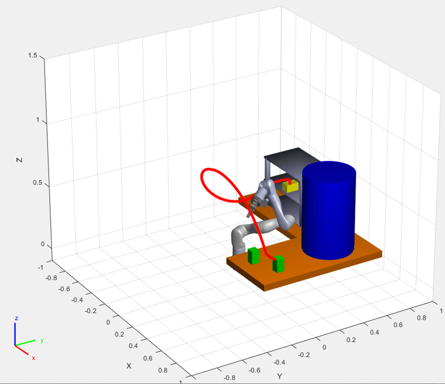
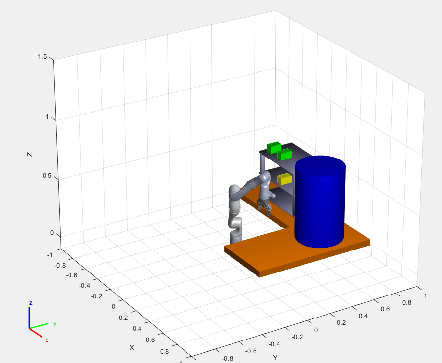
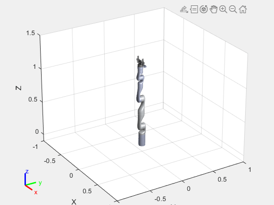
Visualize the Pick-and-Place Action
The example uses the interactiveRigidBodyTree object for robot visualization. The visualization shows the robot in the working area as it moves parts around. The robot avoids obstacles in the environment (blue cylinder) and places objects on the top or bottom shelf based on their classification. The robot continues working until all parts have been placed.