Main Content

manipulatorRRT

Plan motion for rigid body tree using bidirectional RRT

Since R2020b

Description

The manipulatorRRT object is a single-query planner for manipulator arms that uses the bidirectional rapidly exploring random trees (RRT) algorithm with an optional connect heuristic to potentially increase speed.

The bidirectional RRT planner creates two trees with root nodes at the specified start and goal configurations. To extend each tree, the planner generates a random configuration and, if valid, takes a step from the nearest node based on the MaxConnectionDistance property. After each extension, the planner attempts to connect between the two trees using the new extension and the closest node on the opposite tree. Invalid configurations or connections that collide with the environment are not added to the tree.

For a greedier search, enabling the EnableConnectHeuristic property disables the limit on the MaxConnectionDistance property when connecting between the two trees.
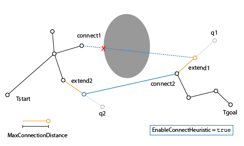
Image showing the extension of the two branching trees from start and end goal. When the EnableConnectHeurist is true, the connection steps are not limited by the max connection distance.

Setting the EnableConnectHueristic property to false limits the extension distance when connecting between the two trees to the value of the MaxConnectionDistance property.
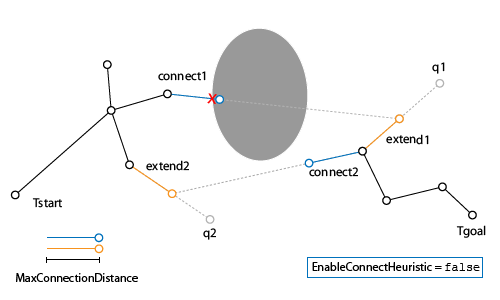
Image showing the extension of the two branching trees from start and end goal. When the EnableConnectHeurist is false, the connection steps are limited by the max connection distance.

The object uses a rigidBodyTree robot model to generate the random configurations and intermediate states between nodes. Collision objects are specified in the robot model to validate the configurations and check for collisions with the environment or the robot itself.

To plan a path between a start and a goal configuration, use the plan object function. After planning, you can interpolate states along the path using the interpolate object function. To attempt to shorten the path by trimming edges, use the shorten object function.

To specify a region to sample end-effector poses near the goal configuration, create a workspaceGoalRegion object and specify it as the goalRegion input to the plan object function. To change the probability of sampling additional goal configurations, specify the WorkspaceGoalRegionBias property.

For more information about the computational complexity, see Planning Complexity.

Creation

Description

rrt = manipulatorRRT(robotRBT,{}) creates a bidirectional RRT planner for the specified rigidBodyTree robot model. The empty cell array indicates that there are no obstacles in the environment.

example

rrt = manipulatorRRT(robotRBT,collisionObjects) creates a planner for a robot model with collision objects placed in the environment. The planner checks for collisions with these objects.

rrt = manipulatorRRT(___,Map=map) specifies a 3-D occupancy map map to represent the environment. This requires Navigation Toolbox™.

example

rrt = manipulatorRRT(___,Name=Value) specifies properties using one or more name-value arguments in addition to any input arguments from the previous syntaxes.

Input Arguments

expand all

3-D occupancy map representing the environment, specified as a occupancyMap3D (Navigation Toolbox) object. Note that the manipulatorRRT object does not deep copy the specified map and instead holds the handle to the specified map.

Specifying this input argument requires Navigation Toolbox.

Properties

expand all

Maximum length between planned configurations, specified as a positive scalar. The object computes the length of the motion as the Euclidean distance between the two joint configurations. During the extension process, this is the maximum distance a configuration can change.

When revolute joints have infinite limits, differences between two joint positions are calculated using the angdiff function.

If the EnableConnectheuristic property is set to true, the object ignores this distance when connecting the two trees during the connect stage.

Data Types: double

Distance resolution for validating motion between configurations, specified as a positive scalar. The validation distance determines the number of interpolated nodes between two adjacent nodes in the tree. The object validates each interpolated node by checking for collisions with the robot and the environment.

Data Types: double

Maximum number of random configurations generated, specified as a positive integer.

Data Types: double

Directly join trees during the connect phase of the planner, specified as a logical 1 (true) or 0 (false). Setting this property to true causes the object to ignore the MaxConnectionDistance property when attempting to connect the two trees together.

Data Types: logical

Probability to sample a goal state from the workspace goal region, specified as a positive value in the range [0,1). The bias defines the probability to add additional goal states to the tree from the workspaceGoalRegion object. When this value is set to zero, the workspaceGoalRegion object still samples a single goal for the planner to plan to.

Increasing this value increases the likelihood of reaching a goal state in the goal region, but may lead to longer planning times because each new goal state adds additional complexity for planning.

Dependency

You must use the goalRegion input when calling the plan object function.

Data Types: double

Ignore self collisions during planning, specified as a logical. If this property is set to true, the plan function skips checking between bodies for collisions and only compares the bodies to the environment. By not checking for self-collisions, you may improve the speed of the planning phase.

Data Types: logical

Body pairs skipped for checking self-collisions, specified as "parent", "adjacent", or a p-by-2 cell array of character vectors:

Data Types: char | string

Object Functions

planPlan path using RRT for manipulators
interpolateInterpolate states along path from RRT
shortenTrim edges to shorten path from RRT

Examples

collapse all

Use the manipulatorRRT object to plan a path for a rigid body tree robot model in an environment with obstacles. Visualize the planned path with interpolated states.

Load a robot model into the workspace. Use the KUKA LBR iiwa© manipulator arm.

robot = loadrobot("kukaIiwa14","DataFormat","row");

Generate the environment for the robot. Create collision objects and specify their poses relative to the robot base. Visualize the environment.

env = {collisionBox(0.5, 0.5, 0.05) collisionSphere(0.3)};
env{1}.Pose(3, end) = -0.05;
env{2}.Pose(1:3, end) = [0.1 0.2 0.8];

show(robot);
hold on
show(env{1})
show(env{2})

Figure contains an axes object. The axes object with xlabel X, ylabel Y contains 31 objects of type patch, line. These objects represent world, iiwa_link_0, iiwa_link_1, iiwa_link_2, iiwa_link_3, iiwa_link_4, iiwa_link_5, iiwa_link_6, iiwa_link_7, iiwa_link_ee, iiwa_link_ee_kuka, iiwa_link_0_mesh, iiwa_link_1_mesh, iiwa_link_2_mesh, iiwa_link_3_mesh, iiwa_link_4_mesh, iiwa_link_5_mesh, iiwa_link_6_mesh, iiwa_link_7_mesh.

Create the RRT planner for the robot model.

rrt = manipulatorRRT(robot,env);
rrt.SkippedSelfCollisions = "parent";

Specify a start and a goal configuration.

startConfig = [0.08 -0.65 0.05 0.02 0.04 0.49 0.04];
goalConfig =  [2.97 -1.05 0.05 0.02 0.04 0.49 0.04];

Plan the path. Due to the randomness of the RRT algorithm, set the rng seed for repeatability.

rng(0)
path = plan(rrt,startConfig,goalConfig);

Visualize the path. To add more intermediate states, interpolate the path. By default, the interpolate object function uses the value of ValidationDistance property to determine the number of intermediate states. The for loop shows every 20th element of the interpolated path.

interpPath = interpolate(rrt,path);
clf
for i = 1:20:size(interpPath,1)
    show(robot,interpPath(i,:));
    hold on
end
show(env{1})
show(env{2})
hold off

Figure contains an axes object. The axes object with xlabel X, ylabel Y contains 437 objects of type patch, line. These objects represent world, iiwa_link_0, iiwa_link_1, iiwa_link_2, iiwa_link_3, iiwa_link_4, iiwa_link_5, iiwa_link_6, iiwa_link_7, iiwa_link_ee, iiwa_link_ee_kuka, iiwa_link_0_mesh, iiwa_link_1_mesh, iiwa_link_2_mesh, iiwa_link_3_mesh, iiwa_link_4_mesh, iiwa_link_5_mesh, iiwa_link_6_mesh, iiwa_link_7_mesh.

Specify a goal region in your workspace and plan a path within those bounds. The workspaceGoalRegion object defines the bounds on the xyz-position and zyx Euler orientation of the robot end effector. The manipulatorRRT object plans a path based on that goal region and samples random poses within the bounds.

Load an existing robot model as a rigidBodyTree object.

robot = loadrobot("kinovaGen3", "DataFormat", "row");
ax = show(robot);

Figure contains an axes object. The axes object with xlabel X, ylabel Y contains 25 objects of type patch, line. These objects represent base_link, Shoulder_Link, HalfArm1_Link, HalfArm2_Link, ForeArm_Link, Wrist1_Link, Wrist2_Link, Bracelet_Link, EndEffector_Link, Shoulder_Link_mesh, HalfArm1_Link_mesh, HalfArm2_Link_mesh, ForeArm_Link_mesh, Wrist1_Link_mesh, Wrist2_Link_mesh, Bracelet_Link_mesh, base_link_mesh.

Create Path Planner

Create a rapidly-exploring random tree (RRT) path planner for the robot. This example uses an empty environment, but this workflow also works well with cluttered environments. You can add collision objects to the environment like the collisionBox or collisionMesh object.

planner = manipulatorRRT(robot,{});
planner.SkippedSelfCollisions="parent";

Define Goal Region

Create a workspace goal region using the end-effector body name of the robot.

Define the goal region parameters for your workspace. The goal region includes a reference pose, xyz-position bounds, and orientation limits on the zyx Euler angles. This example specifies bounds on the xy-plane in meters and allows rotation about the z-axis in radians.

goalRegion = workspaceGoalRegion(robot.BodyNames{end}); 
goalRegion.ReferencePose = trvec2tform([0.5 0.5 0.2]);
goalRegion.Bounds(1, :) = [-0.2 0.2];    % X Bounds
goalRegion.Bounds(2, :) = [-0.2 0.2];    % Y Bounds
goalRegion.Bounds(4, :) = [-pi/2 pi/2];  % Rotation about the Z-axis

You can also apply a fixed offset to all poses sampled within the region. This offset can account for grasping tools or variations in dimensions within your workspace. For this example, apply a fixed transformation that places the end effector 5 cm above the workspace.

goalRegion.EndEffectorOffsetPose = trvec2tform([0 0 0.05]);
hold on
show(goalRegion);

Figure contains an axes object. The axes object with xlabel X, ylabel Y contains 35 objects of type line, patch. These objects represent base_link, Shoulder_Link, HalfArm1_Link, HalfArm2_Link, ForeArm_Link, Wrist1_Link, Wrist2_Link, Bracelet_Link, EndEffector_Link, Shoulder_Link_mesh, HalfArm1_Link_mesh, HalfArm2_Link_mesh, ForeArm_Link_mesh, Wrist1_Link_mesh, Wrist2_Link_mesh, Bracelet_Link_mesh, base_link_mesh.

Plan Path To Goal Region

Plan a path to the goal region from the robot's home configuration. Due to the randomness in the RRT algorithm, this example sets the rng seed to ensure repeatable results.

rng(0)
path = plan(planner,homeConfiguration(robot),goalRegion);

Show the robot executing the path. To visualize a more realistic path, interpolate points between path configurations.

interpConfigurations = interpolate(planner,path,5);

for i = 1:size(interpConfigurations,1)
    show(robot,interpConfigurations(i,:),"PreservePlot",false);
    set(ax,'ZLim',[-0.05 0.75],'YLim',[-0.05 1],'XLim',[-0.05 1],...
        'CameraViewAngle',5)
  
    drawnow
end
hold off

Figure contains an axes object. The axes object with xlabel X, ylabel Y contains 35 objects of type line, patch. These objects represent base_link, Shoulder_Link, HalfArm1_Link, HalfArm2_Link, ForeArm_Link, Wrist1_Link, Wrist2_Link, Bracelet_Link, EndEffector_Link, Shoulder_Link_mesh, HalfArm1_Link_mesh, HalfArm2_Link_mesh, ForeArm_Link_mesh, Wrist1_Link_mesh, Wrist2_Link_mesh, Bracelet_Link_mesh, base_link_mesh.

Adjust End-Effector Pose

Notice that the robot arm approaches the workspace from the bottom. To flip the orientation of the final position, add a pi rotation to the Y-axis for the reference pose.

goalRegion.EndEffectorOffsetPose = ... 
    goalRegion.EndEffectorOffsetPose*eul2tform([0 pi 0],"ZYX");

Replan the path and visualize the robot motion again. The robot now approaches from the top.

hold on
show(goalRegion);
path = plan(planner,homeConfiguration(robot),goalRegion);

interpConfigurations = interpolate(planner,path,5);

for i = 1 : size(interpConfigurations,1)
    show(robot, interpConfigurations(i, :),"PreservePlot",false);
    set(ax,'ZLim',[-0.05 0.75],'YLim',[-0.05 1],'XLim',[-0.05 1])
    drawnow;
end
hold off

Figure contains an axes object. The axes object with xlabel X, ylabel Y contains 45 objects of type line, patch. These objects represent base_link, Shoulder_Link, HalfArm1_Link, HalfArm2_Link, ForeArm_Link, Wrist1_Link, Wrist2_Link, Bracelet_Link, EndEffector_Link, Shoulder_Link_mesh, HalfArm1_Link_mesh, HalfArm2_Link_mesh, ForeArm_Link_mesh, Wrist1_Link_mesh, Wrist2_Link_mesh, Bracelet_Link_mesh, base_link_mesh.

Load the Kinova Gen 3 robot.

rbt = loadrobot("kinovagen3",DataFormat="row");

Create a 3-D occupancy map and set the coordinate at [0.4 0.0 0.4] to occupied.

map = occupancyMap3D(10);
map.setOccupancy([0.4 0.0 0.4],1);

Display the robot in the map.

show(map);
hold on
show(rbt);
axis("equal")
xlim([-1,1.0])
ylim([-1,1.0])
zlim([-0.5,1.2])

Define a start configuration.

startconfig = [2.2131,-1.3950,0.1618,0.2053,-0.1624,1.1684,-2.1886];

Define a goal configuration that is the same as the start configuration except for the first joint.

goalconfig = startconfig;
goalconfig(1) = 3.4;

Create the manipulator RRT planner for the robot and specify the map as the environment using the Map argument.

planner = manipulatorRRT(rbt,{},Map=map);
planner.ValidationDistance=0.1;
planner.MaxConnectionDistance=0.2;
planner.SkippedSelfCollisions="parent";

Plan a path between the start and goal configuration. Then interpolate between the paths.

plannedpath = plan(planner,startconfig,goalconfig);
interpoalatedpath = interpolate(planner,plannedpath);

Animate the robot following the path.

rc=rateControl(10);
view([pi/3,pi/2,pi/4]);
for i = 1:size(interpoalatedpath,1)
    show(rbt,interpoalatedpath(i,:),FastUpdate=true,PreservePlot=false);
    waitfor(rc);
end

Figure contains an axes object. The axes object with title Occupancy Map, xlabel X [meters], ylabel Y [meters] contains 26 objects of type patch, line.

Tips

Planning Complexity

  • When planning the motion between nodes in the tree, a set of configurations are generated and validated. This computation time of the planner is proportional to the number of configurations generated. The number of configurations between nodes is controlled by the ratio of the MaxConnectionDistance and ValidationDistance properties. To improve planning time, consider increasing the validation distance or decreasing the max connection distance.

  • Validating each configuration has a complexity of O(mn+m2), where m is the number of collision bodies in the rigidBodyTree object and n is the number of collision objects in worldObjects. Using large numbers of meshes to represent your robot or environment increases the time for validating each configuration.

Infinite Joint Limits

  • If your rigidBodyTree robot model has joint limits that have infinite range (e.g. revolute joint with limits of [-Inf Inf]), the manipulatorRRT object uses limits of [-1e10 1e10] to perform uniform random sampling in the joint limits.

References

[1] Kuffner, J. J., and S. M. LaValle. “RRT-Connect: An Efficient Approach to Single-Query Path Planning.” In Proceedings 2000 ICRA. Millennium Conference. IEEE International Conference on Robotics and Automation. Symposia Proceedings (Cat. No.00CH37065), 2:995–1001. San Francisco, CA, USA: IEEE, 2000. https://doi:10.1109/ROBOT.2000.844730.
Extended Capabilities

C/C++ Code Generation
Generate C and C++ code using MATLAB® Coder™.

Version History

Introduced in R2020b

expand all