Main Content

Report Execution Order of Tasks and Blocks in Simulink Systems

This example shows how to create a report that displays information about all tasks executed by a model and the order in which blocks execute during each task.

Block execution can be separated into different tasks based on sample time if the Treat each discrete rate as a separate task configuration parameter is selected. Export-function models and systems containing certain blocks, such as asynchronous interrupts or event-triggered subsystems, also group block execution into different tasks. See Control and Display Execution Order for more information on viewing task information and block execution order in Simulink®.

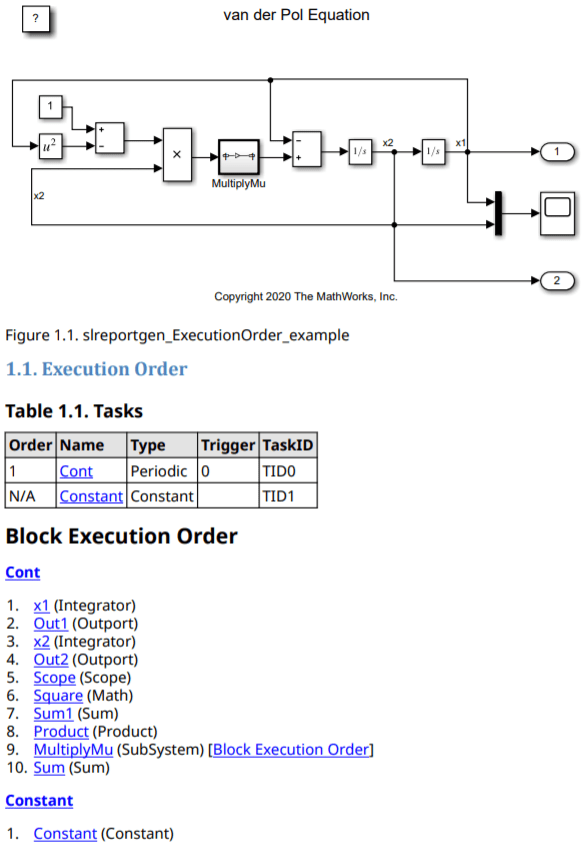
This image shows a diagram of the sample model slreportgen_demo_ExecutionOrder and the task summary and block execution order for the model.

Because the model is a continuous system, the main task, Cont, has a sample time value of 0. In all models, constant blocks are separated into Constant tasks.

MultiplyMu is a nonvirtual subsystem. By default, nonvirtual subsystem entries in a block execution order list contain a link to the block execution order list for that subsystem. Alternatively, you can configure the ExecutionOrder reporter options to display subsystem blocks as a nested list.

Open Model

Open a model. This example uses a single-tasking model, that is, all blocks except constant blocks execute during the same task.

model = "slreportgen_ExecutionOrder_example";
open_system(model);

Report Setup

Import the Report Generator API namespaces so you do not have to use long, fully qualified class names.

import mlreportgen.report.*
import slreportgen.report.*
import slreportgen.finder.*

Create and open a Simulink report object. To create a Microsoft® Word, HTML, or single-file HTML report, change "pdf" to "docx", "html", or "html-file", respectively.

rpt = slreportgen.report.Report(model + "_Report","pdf");
open(rpt);

Add a title page and table of contents.

titlepage = TitlePage("Title",model + ": Execution Order Report","Author","Jane Doe");
add(rpt,titlepage);
toc = TableOfContents();
add(rpt, toc);

Report on Task and Block Execution Order

Find and loop through all systems in the model.

finder = SystemDiagramFinder(model);
while hasNext(finder)
    system = next(finder);

Create a new chapter and add the diagram result.

    ch = Chapter("Title",sprintf("System %s",system.Name));
    add(ch,system);

Report the execution order of the system only if it is a block diagram or a nonvirtual subsystem. Blocks within virtual subsystems are reported in the parent's block execution order.

    isNonvirtualSubsystem = strcmp(system.Type, "Simulink.SubSystem") ...
        && strcmp(get_param(system.Object, "IsSubsystemVirtual"), "off");
    if strcmp(system.Type,"Simulink.BlockDiagram") || isNonvirtualSubsystem

Create an Execution Order section and an ExecutionOrder reporter.

        eoSect = Section("Execution Order");
        eoRptr = ExecutionOrder(system);        

For subsystems, set the ExecutionOrder options so that task details are not reported, because this information is already reported by the parent block diagram execution order.

        if isNonvirtualSubsystem
            eoRptr.ShowTaskDetails = false;
        end

Add the ExecutionOrder reporter to the Execution Order chapter, and add the chapter to the report.

        add(eoSect,eoRptr);
        add(ch,eoSect);
    end

Create a section to include details about each block in the system. Blocks included in ExecutionOrder block execution order lists link to the corresponding block details in this section.

    blkSect = Section("Blocks");
    blkFinder = BlockFinder(system);
    results = find(blkFinder);
    add(blkSect,results);
    add(ch,blkSect);

Add the chapter to the report.

    add(rpt,ch);
end

Close and View the Report

close(rpt);
rptview(rpt);

View Sample Reports

To see how execution order is reported for other types of models, view the sample reports available with this example.

Multitasking Models

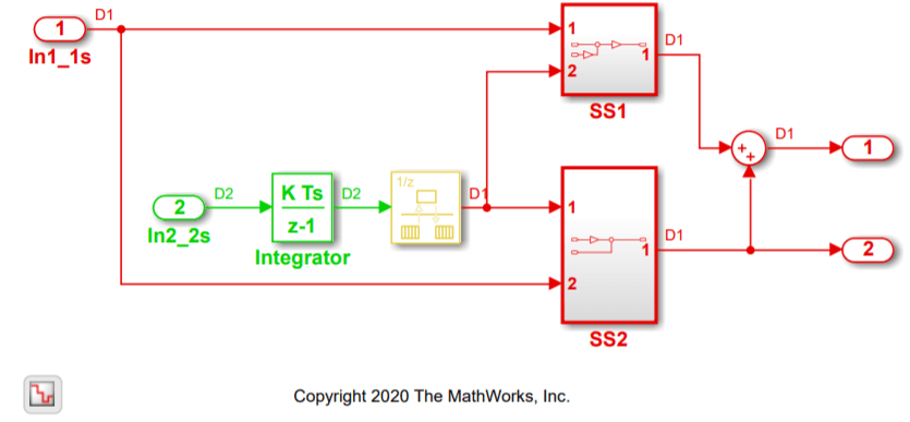
The sample model slreportgen_demo_Multitasking is configured to treat each discrete sample time as a separate task. The sample time for blocks In1_1s, SS1, and SS2 is 1 second, and the sample time for block In2_2s is 2 seconds.

The model is also configured to display blocks color-coded by sample time. Blocks that execute at a 1 second sample time are red, and blocks that execute at a 2 second sample time are green. Multirate blocks, such as the rate-transition block between the Integrator block and the two subsystems, are yellow. To programmatically configure a model in this way, execute this command:

set_param(model, "SampleTimeColors", "on");

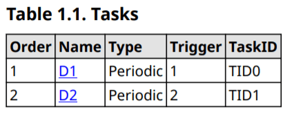
The execution order for this model reports two tasks. The Trigger column of the task details table reports the sample time, in seconds, for each task.

The model blocks are separated by task. The rate-transition block executes during both tasks, so it is included in both lists. However, only its output port executes during task D1, and only its input port executes during task D2.

To view the full sample report, execute this command:

rptview("slreportgen_demo_Multitasking_Report.pdf")

Nonperiodic Tasks

Some tasks, such as those created by asynchronous interrupts or event listeners, do not execute based on sample time. For example, the sample model slreportgen_demo_InitResetTerm uses three subsystems with the execution controlled by event listeners. Each event listener is configured to execute a subsystem when it receives an initialize, reset, or terminate function-call event.

The initialize, reset, and terminate events are reported as separate tasks in the execution order. Their execution does not directly depend on the sample time of the model, so they are not given an order number in the task table. The SourceBlock column denotes which block defines the task.

To view the full sample report, execute this command:

rptview("slreportgen_demo_InitResetTerm_Report.pdf")

Conditional Execution

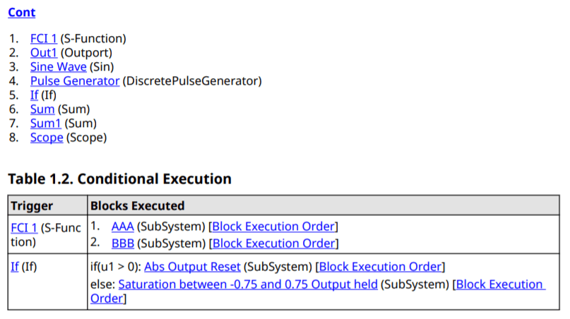
The sample model slreportgen_demo_ConditionalExecution contains an If block and a Function-Call Generator block that control when certain subsystems within the model execute.

The conditionally executed subsystems are not reported in the block execution order list because they do not necessarily execute at every time step. Instead, they are included in a Conditional Execution table that is reported after the block execution order list.

To view the full sample report, execute this command:

rptview("slreportgen_demo_ConditionalExecution_Report.pdf")

See Also

Related Topics