Stimulus Patterns in Parallel Link Design
You can specify stimulus patterns independently for each transfer net type (Data, Clock and Strobe) or designator using the Parallel Link Designer app. To create and manage stimulus patterns, launch the Stimuli dialog box from Setup > Stimulus from the app toolbar.
The Parallel Link Designer app supports two kinds of stimuli:
Classic Stimuli — Classical stimulus patterns for parallel link design projects.
STAT Stimuli — PRBS stimulus patterns used for STAT mode simulations.
The Stimuli dialog box has a table of stimulus patterns with columns for the name, length in bits and description of each stimulus pattern. You can edit, delete, copy, or add new stimulus patterns.
Classic Stimulus
There are three default classic stimulus patterns for each transfer net:
| Transfer net type | Stimulus pattern |
|---|---|
| Data | default_data |
| default_data_victim | |
| default_data_aggressor | |
| Clock | default_clock |
| default_clock_victim | |
| default_clock_aggressor | |
| Strobe | default_strobe |
| default_strobe_victim | |
| default_strobe_aggressor |
You cannot delete or rename the default stimuli, only edit their patterns. The victim and aggressor patterns are used in pre-layout coupled/SSO (widebus) simulation mode.
The default_data, default_clock and
default_strobe patterns are used in pre-layout and post-layout
simulations. The Transfer Net Type controls the stimulus used for a simulation. The default
stimulus patterns can be edited and can be up to 4000 bits long.
In pre-layout analysis each designator can have its own stimulus. You can create and use new stimulus patterns for individual designators.
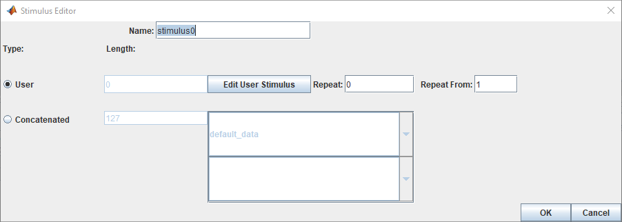
Stimulus Editor for Classic Stimuli
You can create a new classic stimulus or edit an existing one by using the Stimulus Editor dialog box. To access the Stimulus Editor dialog box, first open the Stimuli dialog box by double clicking on a designator symbol and clicking the Stimulus button. Then select the stimulus you want to edit and click the Edit button to open the Stimulus Editor dialog box.

A classic stimulus can be of two types:
User — user defined series of ones and zeroes.
Concatenated — one or more User stimulus patterns combined sequentially.
Each stimulus has a name. To create a User stimulus, select User and click Edit User Stimulus to launch the User Stimulus Editor dialog box.
To create a Concatenated stimulus, select Concatenated and then select one or more stimulus names in the table. In the simulation netlist the stimuli is concatenated with the stimulus at the top of the list appearing first in the netlist. The Length parameter shows the length of the concatenated stimuli.
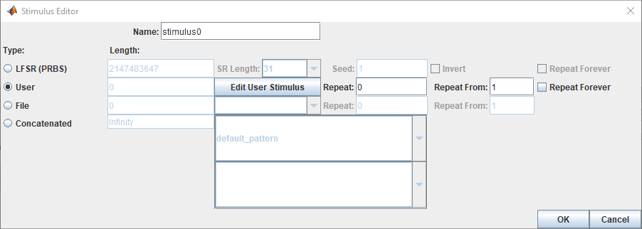
Stat Mode Stimuli
You can specify a PRBS stimulus patterns for the STAT mode time domain analysis in the Parallel Link Designer app. If the specified pattern for a designator has fewer bits than the simulation length, the pattern is repeated from the first bit of the pattern. If the pattern is longer than the simulation length the simulation will end at the time specified by Time Domain Stop parameter.
Types of STAT Mode Stimulus Patterns
| Stimulus Pattern | Description |
|---|---|
| LFSR (Linear Feedback Shift Register) | PRBS generated from a shift register with feedback. You need to specify how many bits to generate from the shift register (length), the shift register length (SR length), and the initial value of the shift register (seed) |
| User | User defined series of ones and zeros. |
| File | Stimulus defined in a file. |
| Concatenated | Created from one of more stimulus patterns. |
Note
LFSR and File stimulus patterns are used for only STAT mode stimuli.
Stimulus Editor for STAT Mode Stimuli
The User Stimulus Editor is used to create a stimulus.

Using Stimulus Editor to Create Stimuli
The User Stimulus Editor dialog box is used to create a user defined stimulus. You can directly type in the ones and zeroes in the main window. You can also add a specific number of ones, zeroes or zero-one sequences. After completing entering your desired sequence, click OK to return to the Stimulus Editor dialog box. The Stimulus Editor dialog box contains the following parameters about the User stimulus:
Length — the length of the pattern created in the User Stimulus Editor.
Repeat — the number of times to repeat the pattern. For a pattern of length n, setting Repeat to
0results in a pattern of length n, setting Repeat to1results in a pattern of length2nand so on.Repeat From — the bit position to repeat from. Bit 1 is the first bit in the pattern.
PDA Stimulus
You can use the Parallel Link Designer app to determine the worst-case pattern through Peak Distortion Analysis (PDA) and use that stimulus for a designator by selecting PDA in the Designator Element Properties dialog box. When PDA stimulus is selected, the Generate SPICE process during simulation first creates step response simulations. The step response simulations are processed to find the worst-case pattern. The normal Transfer Net simulations are then generated using the PDA pattern as the stimulus.
The Generate SPICE Log (Logs > SI/Timing SPICE Generation Log) and Generate SPICE Report (Reports > SI/Timing SPICE Generation Report) have details and any errors and warnings from the process. The log is also included in the Errors & Warnings dialog box.
Using Stimulus Pattern
To specify a stimulus pattern (other than the default) on an individual designator basis, open the Designator Element Properties dialog box by double clicking on any designator in the Pre-Layout Analysis tab. You can also access the dialog box by clicking on the Properties button in the Transfer Net Properties dialog box in the pre- or post-layout. In the Designator Element Properties dialog box, select the desired stimulus pattern from the Stimulus drop-down menu.