Hit Crossing
Detect crossing point
Libraries:
Simulink /
Discontinuities
Simulink /
Messages & Events
HDL Coder /
Discontinuities
SimEvents
Description
The Hit Crossing block detects when the input reaches the Hit crossing offset parameter value in the direction specified by the Hit crossing direction property.
You can configure the block to output a 1 or 0 signal,
a message, or a function-call event. See
Output for more information.
Examples
Building a Clutch Lock-Up Model
Use Simulink® to model and simulate a rotating clutch system. Although modeling a clutch system is difficult because of topological changes in the system dynamics during lockup, this example shows how enabled subsystem can easily handle such problems. We illustrate how to employ important Simulink modeling concepts in the creation of the clutch simulation. Designers can apply these concepts to many models with strong discontinuities and constraints that may change dynamically.
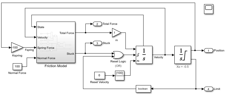
Model Stick-Slip Friction and Hard Stops in Mass-Spring-Damper System
One way you can incorporate hard stops and friction changes from stick-slip motion into a mass-spring-damper model.
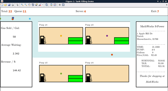
Modeling Hybrid Systems - Tank Filling
A hybrid system with both continuous time and discrete event sections. The discrete event part models tanks, represented by entities, which are being queued and need to be filled up. Each tank has a "Capacity" attribute. The continuous time part models the process of filling up a tank, modeled by an Integrator. When a tank is filled to capacity, this event can be detected by a Hit Crossing block, which will generate a message corresponding to this event. The generated message will trigger the server to release the tank.
Ports
Input
Input signal that the block detects when it reaches the offset in the specified direction.
Data Types: double
Output
Output indicating if the input signal crossed the hit offset. This port is visible only when you select the Show output port parameter check box.
Signal Output
If you select the Show output port check box and set the
Output type parameter to
Signal, the block output indicates when
the crossing occurs.
If the input signal is exactly the value of the offset value after the hit crossing is detected in the specified direction, the block continues to output a value of 1.
If the input signals at two adjacent points brackets the offset value, the block outputs a value of 1 at the second time step.
If the Show output port check box is not selected, the block ensures that the simulation finds the crossing point but does not generate output.
If the initial signal is equal to the offset value, the block outputs 1 only if the Hit crossing direction property is set to
either.If Boolean logic signals are enabled, then the output is a
Boolean.
Message Output
The Hit Crossing block can also output a message when the
Output type parameter is set to
Message.
If the input signal crosses the offset value in the specified direction, the block outputs a message.
If the input signal reaches the offset value in the specified direction and remains there, block outputs one message at the hit time and one message when the signal leaves the offset value.
If the initial input signal is equal to the offset value, the block outputs a message with
Crossing TypevalueNoneonly if the Hit crossing direction is set toeither.
The message output signal is a struct
with four fields.
Note
If the message output signal crosses model reference boundaries or is used as an input to a Stateflow® chart, you need to create a bus object for the message. See Tips.
Function-Call Output
The Hit Crossing block can also output a function-call event when the
Output type parameter is set to
Function-Call.
Each time the input signal crosses the offset value in the specified direction, the block outputs a single function-call event.
The function-call event can be sent to the function-call input port of a function-call subsystem or function-call model.
The output is equivalent to the output of a Function-Call Generator block at each time step with the Number of iterations parameter of that block set to
1.
This field shows the direction in which the signal crosses
the Hit crossing offset value.
Negative, Zero, and Positive are defined relative to the
offset value. The data type is
slHitCrossingType which is an
enumerated data type. See Use Enumerated Data in Simulink Models for more
information. For example, if
HitCrossingOffset is set to 2, a
rising signal crossing this offset value would be recorded
as a NegativeToPositive hit crossing.
Note
A hit crossing is recorded based on the
Hit crossing direction
setting. In other words, if you set Hit
crossing direction to detect a
falling hit crossing, a
NegativeToPositive hit is not
recorded.
Note
In a SimEvents® block, if the Crossing
Type of an entity is a
NegativeToPositive hit crossing
then entity.CrossingType ==
slHitCrossingType.NegativeToPositive
returns logical 1 (true).
If the signal reaches the
HitCrossingOffset value and holds it,
a single NegativeToZero or
PositiveToZero, depending on the
direction, hit is registered at the time of the hit
crossing.
Data Types: slHitCrossingType
For n signals being passed to the Hit Crossing block, this field denotes which signal had a hit crossing event. For a matrix input, this field follows MATLAB® linear indexing. See Array Indexing.
Data Types: uint32
Time T of the hit crossing event.
Data Types: double
Hit crossing offset value as specified by the Hit crossing offset parameter.
Data Types: double
Data Types: double | Boolean | struct
Parameters
Specify the value the block detects when the input crosses in the direction specified by Hit crossing direction.
Programmatic Use
Block Parameter:
HitCrossingOffset |
| Type: character vector |
| Values: real values |
Default:
'0' |
Direction from which the input signal approaches the hit crossing offset for a crossing to be detected.
When set to either, the block serves as an
almost equal block, useful in working around
limitations in finite mathematics and computer precision. Used for these
reasons, this block might be more convenient than adding logic to your model
to detect this condition.
When the Hit crossing direction property is set to
either and the model uses a fixed-step
solver, the block has the following behavior. If the output signal is 1, the
block sets the output signal to 0 at the next time step, unless the input
signal equals the offset value.
Programmatic Use
Block Parameter:
HitCrossingDirection |
| Type: character vector |
Values: 'either' |
'rising' |
'falling' |
Default:
'either' |
If selected, create an output port on the block icon.
Programmatic Use
Block Parameter:
ShowOutputPort |
| Type: character vector |
Values:
'off' | 'on' |
Default:
'on' |
When Output type is set to
Signal, the output signal is set to one
whenever the input signal crosses the Hit crossing
offset value in the Hit crossing
direction and is zero at other times.
When the Output type is set to Message,
the output signal becomes a message.
When Output type is set to Function-Call,
the output signal becomes a function-call event.
Programmatic Use
Block Parameter:
HitCrossingOutputType |
| Type: character vector |
Values:
'Signal' | 'Message' |
'Function-Call' |
Default:
'Signal' |
Select to enable zero-crossing detection. For more information, see Zero-Crossing Detection.
Programmatic Use
Parameter:
ZeroCross |
| Type: character vector, string |
Values:
'on' | 'off' |
Default:
'on' |
Block Characteristics
Data Types |
|
Direct Feedthrough |
|
Multidimensional Signals |
|
Variable-Size Signals |
|
Zero-Crossing Detection |
|
Tips
If the Hit Crossing block is configured to output a message and the output signal:
Crosses into or out of a referenced model
Is fed to the input of a Stateflow chart
then you need to create a bus object for the message signal. In the
MATLAB Command Window, run Simulink.createHitCrossMessage to
check for and, if needed, create a hit crossing message bus object in the base
workspace.
Set the data type of the corresponding port to Bus:
HitCrossMessage.
Extended Capabilities
Not recommended for production code generation.
Supports only floating point data types for ERT targets.
HDL Coder™ provides additional configuration options that affect HDL implementation and synthesized logic.
This block has one default HDL architecture.
| ConstrainedOutputPipeline | Number of registers to place at
the outputs by moving existing delays within your design. Distributed
pipelining does not redistribute these registers. The default is
|
| InputPipeline | Number of input pipeline stages
to insert in the generated code. Distributed pipelining and constrained
output pipelining can move these registers. The default is
|
| OutputPipeline | Number of output pipeline stages
to insert in the generated code. Distributed pipelining and constrained
output pipelining can move these registers. The default is
|
The Hit crossing direction must be rising or
falling.
HDL code generation is not supported when the Output Type is set to
Message.
Version History
Introduced in R2018a
MATLAB Command
You clicked a link that corresponds to this MATLAB command:
Run the command by entering it in the MATLAB Command Window. Web browsers do not support MATLAB commands.
选择网站
选择网站以获取翻译的可用内容,以及查看当地活动和优惠。根据您的位置,我们建议您选择:。
您也可以从以下列表中选择网站:
如何获得最佳网站性能
选择中国网站(中文或英文)以获得最佳网站性能。其他 MathWorks 国家/地区网站并未针对您所在位置的访问进行优化。
美洲
- América Latina (Español)
- Canada (English)
- United States (English)
欧洲
- Belgium (English)
- Denmark (English)
- Deutschland (Deutsch)
- España (Español)
- Finland (English)
- France (Français)
- Ireland (English)
- Italia (Italiano)
- Luxembourg (English)
- Netherlands (English)
- Norway (English)
- Österreich (Deutsch)
- Portugal (English)
- Sweden (English)
- Switzerland
- United Kingdom (English)


