Main Content

Zero-Crossing Detection

A variable-step solver dynamically adjusts the time step size, causing it to increase when a variable is changing slowly and to decrease when the variable changes rapidly. This behavior causes the solver to take many small steps in the vicinity of a discontinuity because the variable is rapidly changing in this region. This improves accuracy but can lead to excessive simulation times.

Simulink® uses a technique known as zero-crossing detection to accurately locate a discontinuity without resorting to excessively small time steps. Usually this technique improves simulation run time, but it can cause some simulations to halt before the intended completion time.

Simulink uses two algorithms for this purpose: nonadaptive and adaptive. For information about these techniques, see Zero-Crossing Algorithms.

Demonstrating Effects of Excessive Zero-Crossing Detection

This example provides three models that illustrate zero-crossing behavior: example_bounce_two_integrators, example_doublebounce, and example_bounce.

The example_bounce_two_integrators model demonstrates how excessive zero crossings can cause a simulation to halt before the intended completion time unless you use the adaptive algorithm.

The example_bounce model uses a better model design, implementing the dynamics of the ball using a double integrator, than example_bounce_two_integrators.

The example_doublebounce model demonstrates how the adaptive algorithm successfully solves a complex system with two distinct zero-crossing requirements.

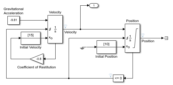
Consider the example_bounce_two_integrators model. It uses two single integrators to compute the vertical velocity and position of the ball over the time of the simulation.

  1. Open the model by running open_system('example_bounce_two_integrators') at the command line.

  2. Once the block diagram appears, set the Solver details > Zero-crossing options > Algorithm parameter in the Solver pane of the Model configuration parameters to Nonadaptive. Set the stop time of the model to 20 s. You can change this setting in the Simulink toolstrip or the Solver pane of the model configuration parameters.

  3. Simulate the model.

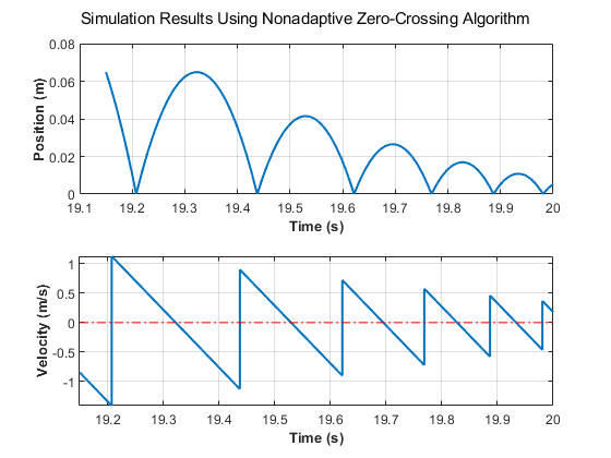
You can now view and analyze the simulation results.

Upon closer examination of the last portion of the simulation, you will see that velocity hovers just above zero.

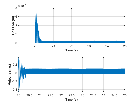
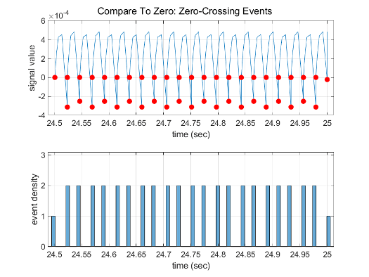
Change the simulation Stop time to 25 s and simulate the model. The simulation stops with an error due to excessive consecutive zero-crossing events at the Compare To Zero and Position blocks.

Simulink will stop the simulation of model 'example_bounce_two_integrators' because the 2 zero crossing signal(s) identified below caused 1000 consecutive zero crossing events in time interval between 20.357636989536076 and 20.357636990631594.
 --------------------------------------------------------------------------------
Number of consecutive zero-crossings : 1000
           Zero-crossing signal name : RelopInput
                          Block type : RelationalOperator
                          Block path : 'example_bounce_two_integrators/Compare To Zero/Compare'
--------------------------------------------------------------------------------
--------------------------------------------------------------------------------
Number of consecutive zero-crossings : 500
           Zero-crossing signal name : x Lower Saturation
                          Block type : Integrator
                          Block path : 'example_bounce_two_integrators/Position'
--------------------------------------------------------------------------------
 

Although you can increase this limit by adjusting the Model Configuration Parameters > Solver > Number of consecutive zero crossings parameter, making that change still does not allow the simulation to go on for 25 s.

Change the Solver details > Zero-crossing options > Algorithm parameter in the Solver pane of the Model configuration parameters to Adaptive and simulate the model again for 25 s.

Zooming in on the last 5 seconds of the simulation, you can see that the results are more complete and closer to the expected analytical solution of the dynamics of a bouncing ball. The amount of chatter you see is a consequence of the system's states approaching zero and is expected in numerical simulations.

The example_bounce model uses a Second-Order Integrator block to model the dynamics of the bouncing ball. This is the preferred method to model the double integration of the ball's dynamics for solver performance. To compare the solver performance for example_bounce_two_integrators and example_bounce, try running the Solver Profiler on both models. For a detailed comparison of both models, see Simulation of Bouncing Ball.

For a side-by-side comparison of adaptive and nonadaptive zero-crossing detection algorithms, see Double Bouncing Ball: Use of Adaptive Zero-Crossing Location.

Preventing Excessive Zero Crossings

Use the following table to prevent excessive zero-crossing errors in your model.

Change TypeChange ProcedureBenefits

Increase the number of allowed zero crossings

Increase the value of the Number of consecutive zero crossings. option on the Solver pane in the Configuration Parameters dialog box.

This may give your model enough time to resolve the zero crossing.

Relax the Signal threshold

Select Adaptive from the Algorithm pull down and increase the value of the Signal threshold option on the Solver pane in the Configuration Parameters dialog box.

The solver requires less time to precisely locate the zero crossing. This can reduce simulation time and eliminate an excessive number of consecutive zero-crossing errors. However, relaxing the Signal threshold may reduce accuracy.

Use the Adaptive algorithm

Select Adaptive from the Algorithm drop-down on the Solver pane in the Configuration Parameters dialog box.

This algorithm dynamically adjusts the zero-crossing threshold, which improves accuracy and reduces the number of consecutive zero crossings detected. With this algorithm you have the option of specifying both the Time tolerance and the Signal threshold.

Disable zero-crossing detection for a specific block

  1. Clear the Enable zero-crossing detection check box on the block's parameter dialog box.

  2. Select Use local settings from the Zero-crossing control pull down on the Solver pane of the Configuration Parameters dialog box.

Locally disabling zero-crossing detection prevents a specific block from stopping the simulation because of excessive consecutive zero crossings. All other blocks continue to benefit from the increased accuracy that zero-crossing detection provides.

Disable zero-crossing detection for the entire model

Select Disable all from the Zero-crossing control pull down on the Solver pane of the Configuration Parameters dialog box.

This prevents zero crossings from being detected anywhere in your model. A consequence is that your model no longer benefits from the increased accuracy that zero-crossing detection provides.

If using the ode15s solver, consider adjusting the order of the numerical differentiation formulas

Select a value from the Maximum order pull down on the Solver pane of the Configuration Parameters dialog box.

For more information, see Maximum order.

Reduce the maximum step size

Enter a value for the Max step size option on the Solver pane of the Configuration Parameters dialog box.

The solver takes steps small enough to resolve the zero crossing. However, reducing the step size can increase simulation time, and is seldom necessary when using the adaptive algorithm.

How the Simulator Can Miss Zero-Crossing Events

The bounce and double-bounce models, in Simulation of Bouncing Ball and Double Bouncing Ball: Use of Adaptive Zero-Crossing Location show that high-frequency fluctuations about a discontinuity (chattering) can cause a simulation to prematurely halt.

It is also possible for the solver to entirely miss zero crossings if the solver error tolerances are too large. This is possible because the zero-crossing detection technique checks to see if the value of a signal has changed sign after a major time step. A sign change indicates that a zero crossing has occurred, and the zero-crossing algorithm searches for the precise crossing time. However, if a zero crossing occurs within a time step, but the values at the beginning and end of the step do not indicate a sign change, the solver steps over the crossing without detecting it.

The following figure shows a signal that crosses zero. In the first instance, the integrator steps over the event because the sign has not changed between time steps. In the second, the solver detects sign change and therefore detects the zero-crossing event.

Consider the two-integrator implementation of the bounce model.

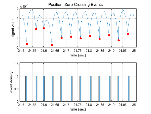
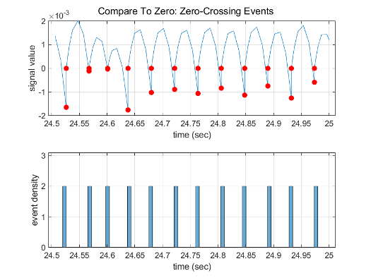
Profiling of the last 0.5 s of the simulation using the Solver Profiler shows that the simulation detects 44 zero-crossing events at the Compare To Zero block and 22 events at the output of the Position block.

Increase the value of the Relative tolerance parameter to 1e-2 instead of the default 1e-3. You can change this parameter in the Solver Details section of the Solver pane in the Configuration Parameters dialog or using set_param to specify RelTol as '1e-2'.

Profiling the last 0.5 s of the simulation with the new relative tolerance of the solver shows that it detects only 24 zero-crossing events at the Compare To Zero block and 12 events at the output of the Position block.

Zero-Crossing Detection in Blocks

A block can register a set of zero-crossing variables, each of which is a function of a state variable that can have a discontinuity. The zero-crossing function passes through zero from a positive or negative value when the corresponding discontinuity occurs. The registered zero-crossing variables are updated at the end of each simulation step, and any variable that has changed sign is identified as having had a zero-crossing event.

If any zero crossings are detected, the Simulink software interpolates between the previous and current values of each variable that changed sign to estimate the times of the zero crossings, that is, the discontinuities.

Note

The Zero-Crossing detection algorithm can bracket zero-crossing events only for signals of data type double.

Blocks That Register Zero Crossings

The following table lists blocks that register zero crossings and explains how the blocks use the zero crossings.

BlockNumber of Zero Crossing Detections

Abs

One, to detect when the input signal crosses zero in either the rising or falling direction.

Backlash

Two, one to detect when the upper threshold is engaged, and one to detect when the lower threshold is engaged.

Compare To Constant

One, to detect when the signal equals a constant.

Compare To Zero

One, to detect when the signal equals zero.

Dead Zone

Two, one to detect when the dead zone is entered (the input signal minus the lower limit), and one to detect when the dead zone is exited (the input signal minus the upper limit).

Enable

One, If an Enable port is inside of a Subsystem block, it provides the capability to detect zero crossings. For details, Using Enabled Subsystems.

From File

One, to detect when the input signal has a discontinuity in either the rising or falling direction

From Workspace

One, to detect when the input signal has a discontinuity in either the rising or falling direction

Hit Crossing

One or two. If there is no output port, there is only one zero crossing to detect when the input signal hit the threshold value. If there is an output port, the second zero crossing is used to bring the output back to 0 from 1 to create an impulse-like output.

If

One, to detect when the If condition is met.

Integrator

If the reset port is present, to detect when a reset occurs.

If the output is limited, there are three zero crossings: one to detect when the upper saturation limit is reached, one to detect when the lower saturation limit is reached, and one to detect when saturation is left.

MinMax

One, for each element of the output vector, to detect when an input signal is the new minimum or maximum.

Rate Limiter Dynamic

Two, one to detect upper limit and the other to detect lower limit

Relational Operator

One, to detect when the specified relation is true.

Relay

One, if the relay is off, to detect the switch-on point. If the relay is on, to detect the switch-off point.

Saturation

Two, one to detect when the upper limit is reached or left, and one to detect when the lower limit is reached or left.

Saturation Dynamic

Two, one to detect upper limit and the other to detect lower limit

Second-Order Integrator

Five, two to detect when the state x upper or lower limit is reached, two to detect when the state dx/dt upper or lower limit is reached, and one to detect when a state leaves saturation.

Sign

One, to detect when the input crosses through zero.

Signal Editor

One, to detect when the input signal has a discontinuity in either the rising or falling direction

Step

One, to detect the step time.

Switch

One, to detect when the switch condition occurs.

Switch Case

One, to detect when the case condition is met.

Trigger

One, If a Triggered port is inside of a Subsystem block, it provides the capability to detect zero crossings. For details, see Using Triggered Subsystems.

Enabled and Triggered Subsystem

Two, one for the enable port and one for the trigger port. For details, see: Using Enabled and Triggered Subsystems

From Spreadsheet

One, to detect when the input signal has a discontinuity in either the rising or falling direction.

Note

Zero-crossing detection is also available for a Stateflow® chart that uses continuous-time mode. See Configure a Stateflow Chart for Continuous-Time Simulation (Stateflow) for more information.

Implementation Example: Saturation Block

An example of a Simulink block that registers zero crossings is the Saturation block. Zero-crossing detection identifies these state events in the Saturation block:

  • The input signal reaches the upper limit.

  • The input signal leaves the upper limit.

  • The input signal reaches the lower limit.

  • The input signal leaves the lower limit.

Simulink blocks that define their own state events are considered to have intrinsic zero crossings. Use the Hit Crossing block to receive explicit notification of a zero-crossing event. See Blocks That Register Zero Crossings for a list of blocks that incorporate zero crossings.

The detection of a state event depends on the construction of an internal zero-crossing signal. This signal is not accessible by the block diagram. For the Saturation block, the signal that is used to detect zero crossings for the upper limit is zcSignal = UpperLimit - u, where u is the input signal.

Zero-crossing signals have a direction attribute, which can have these values:

  • rising — A zero crossing occurs when a signal rises to or through zero, or when a signal leaves zero and becomes positive.

  • falling — A zero crossing occurs when a signal falls to or through zero, or when a signal leaves zero and becomes negative.

  • either — A zero crossing occurs if either a rising or falling condition occurs.

For the Saturation block upper limit, the direction of the zero crossing is either. This enables the entering and leaving saturation events to be detected using the same zero-crossing signal.

Related Topics