Continuous-Time Modeling in Stateflow
Hybrid systems use modal logic to transition from one mode to another in response to physical events and conditions. In these systems, continuous-time dynamics govern each mode. A simple example of this type of hybrid system is a bouncing ball. The ball moves continuously through the air until it hits the ground, at which point a mode change or discontinuity occurs. As a result, the ball suddenly changes direction and velocity. For more information, see Model a Bouncing Ball in Continuous Time.
Simulate hybrid systems that respond to continuous and discrete mode changes by configuring Stateflow® charts for continuous-time modeling. In a Stateflow chart, you can represent modal logic succinctly and intuitively as a series of states, transitions, or flow charts. You can also represent state information as continuous local variables with automatic access to time derivatives.
Continuous-time simulation is supported only in Stateflow charts in Simulink® models. If your continuous system does not contain modal logic, consider using a Simulink model. For more information, see Model a Continuous System (Simulink).
Configure a Stateflow Chart for Continuous-Time Simulation
To enable continuous updating in a Stateflow chart, set the Update method chart property to
Continuous.
By default, zero-crossing detection is enabled. To disable this option, clear the Enable zero-crossing detection check box. For more information, see Disable Zero-Crossing Detection.
Note
You cannot use Moore charts for continuous-time modeling.
Interaction with Simulink Solver
Maintain Mode in Minor Time Steps
During continuous-time simulation, a Stateflow chart updates its mode only in major time steps. In a minor time step, the chart computes outputs based on the state of the chart during the last major time step. For more information, see Continuous Sample Time (Simulink).
Compute Continuous State at Each Time Step
When you define local continuous variables, the Stateflow chart provides programmatic access to their derivatives. The Simulink solver computes the continuous state of the chart at the current time step based on the values of these variables and their derivatives at the previous time step. For more information, see Continuous Versus Discrete Solvers (Simulink).
Register Zero Crossings on State Transitions
To determine when a state transition occurs, a Stateflow chart registers a zero-crossing function with the Simulink solver. When Simulink detects a change of mode, the solver searches forward from the previous major time step to detect when the state transition occurred. For more information, see Zero-Crossing Detection (Simulink).
Disable Zero-Crossing Detection
Zero-crossing detection on state transitions can present a tradeoff between accuracy and performance. When detecting zero crossings, a Simulink model accurately simulates mode changes without unduly reducing step size. For systems that exhibit chattering, or frequent fluctuations between two modes of continuous operation, zero-crossing detection can potentially impact simulation time. Chattering requires a Simulink model to check for zero crossings in rapid succession, which can slow simulation. In these situations, you can:
Disable zero-crossing detection.
Choose a different zero-crossing detection algorithm for your chart.
Modify parameters that control the frequency of zero crossings in your Simulink model.
Open the Configuration Parameters dialog box and, in the Solver pane, change the zero-crossing options for your model. For more information, see Zero-Crossing Detection (Simulink).
Guidelines for Continuous-Time Simulation
To maintain the integrity and smoothness of the results of a continuous-time simulation, constrain your charts to a restricted subset of Stateflow chart semantics. By restricting the semantics, the inputs do not depend on unpredictable factors such as:
The number of minor intervals that the Simulink solver uses in each major time step.
The number of iterations required to stabilize the integration and zero-crossings algorithms.
By minimizing these side effects, a Stateflow chart can maintain its state at minor time steps and update its state only during major time steps. Therefore, a Stateflow chart can compute outputs based on a constant state for continuous time.
Continuous-Time Charts Must Have at Least One State
During continuous-time simulation, a chart updates its outputs at minor time
steps corresponding to the during actions of the active
state. A chart with no states produces no output. To mimic the behavior of a
stateless chart in continuous time, create a single state that calls a graphical
function in its during action.
Update Local Data in entry, exit, and Transition Actions
To maintain precision in continuous-time simulation, update discrete and continuous local data only during major time steps corresponding to state transitions. During state transitions, only these types of actions occur:
State
exitactions, which occur before leaving the state at the beginning of the transition.State
entryactions, which occur after entering the new state at the end of the transition.Transition actions, which occur during the transition.
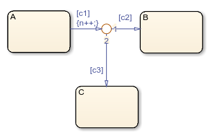
Condition actions on a transition, but only if the transition directly reaches a state. For example, this chart executes the action
n++even when conditionsc2andc3are false. Because there is no state transition, the condition action updatesnin a minor time step and results in an error.
Do not write to local continuous data in state
during actions because these actions occur in minor time
steps.
Compute Derivatives in State during Actions
In minor time steps, a continuous-time chart executes only state
during actions. Because Simulink models read continuous-time derivatives during minor time steps,
compute derivatives in during actions to provide the most
current calculation.
Do Not Read Outputs or Derivatives in State during Actions or in Transition Conditions
In minor time steps, it is possible that outputs and derivatives do not reflect their most current values. To provide smooth outputs, compute values from local discrete data, local continuous data, and chart inputs.
Do Not Call Simulink Functions in State during Actions or in Transition Conditions
You cannot call Simulink functions during minor time steps. Instead, call Simulink functions only in actions that occur during major time steps:
state entry or exit actions and transition
actions. Calling Simulink functions in state during actions or in
transition conditions results in an error during simulation. For more
information, see Reuse Simulink Functions in Stateflow Charts.
Use Discrete Variables to Govern Conditions in during Actions
To prevent mode changes between major time steps, conditions that affect
control flow in during actions depend on discrete variables.
Discrete variables do not change value between major time steps.
Do Not Use Input Events
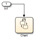
The presence of input events makes a chart behave like a triggered subsystem and unable to simulate in continuous time. For example, this model generates an error if the chart uses a continuous update method.

To mimic the behavior of an input event, pass the input signal through a Hit Crossing block as an input to the continuous-time chart.

Do Not Use Inner Transitions
When a mode change occurs during continuous-time simulation, the
entry action of the destination state indicates to the
Simulink model that a state transition occurred. With an inner transition,
the chart never executes the entry action. For more
information, see Inner Transitions.
Limit Use of Temporal Logic
Do not use event-based temporal logic because in continuous-time simulation, there is no concept of a tick. Use only absolute-time temporal logic for continuous-time simulation. For more information, see Control Chart Execution by Using Temporal Logic.
Do Not Use Change Detection Operators
To implement change detection, Stateflow buffers variables in a way that affects the behavior of charts between a minor time step and the next major time step.
Do Not Modify Operating Point Values
Operating points for continuous-time charts are read-only. You can save an operating point for a continuous-time chart and use it as the initial state for a simulation. However, you cannot modify the state activity or any data values in the operating point. For more information, see Limitations on Operating Points.