对电池中的电压滞后建模
此示例说明了如何使用 Battery Equivalent Circuit 模块仿真可充电电池中的电压滞后现象。开路电压 (OCV) 是指电流为零时电池两端测得的电压差。OCV 是电动势或静电势。对于锂离子电池等可充电或二次电池,在给定的荷电状态和温度状态下,OCV 取决于您之前是否对电池进行过充电或放电。在采用传统插层电极的锂离子电芯中,这种差异通常是由于电极活性材料中存在不同的固相、反应路径滞后以及相关的热力学效应所致。在充电和放电过程中,电极活性材料的锂化与脱锂化通常会根据电池化学性质在不同的荷电状态下产生不同的电极固相。
不同晶格常数的固相在电极颗粒表面同时存在并共存,会在相界面上产生机械应力。该边界基本上作为电流流动的附加路径电阻,为了克服这一障碍,会自然产生过电势。电极/电解质界面处的这些相界取决于电池是处于放电(阴极锂化)还是充电(阳极锂化)状态。另一方面,由于必须激活不同的或不对称的反应路径才能发生充电或放电过程,因此会发生反应路径滞后。Van der Ven 等 [1] 对滞后现象进行了很好的介绍。
Battery Equivalent Circuit 模块实现了 Gregory Plett [2] 的单状态滞后模型,该模型动态建模了电池活性材料中出现的开路电压与负载路径相关的变化。本示例中的应用和数据基于一种锂离子磷酸铁 (LFP) 电池,该电池由两相正极活性材料组成[3]。此图显示了 Battery Equivalent Circuit 模块封装和电压滞后模型的参数。

打开模型
打开 cellHysteresis 模型。
modelName = 'cellHysteresis';
open_system(modelName);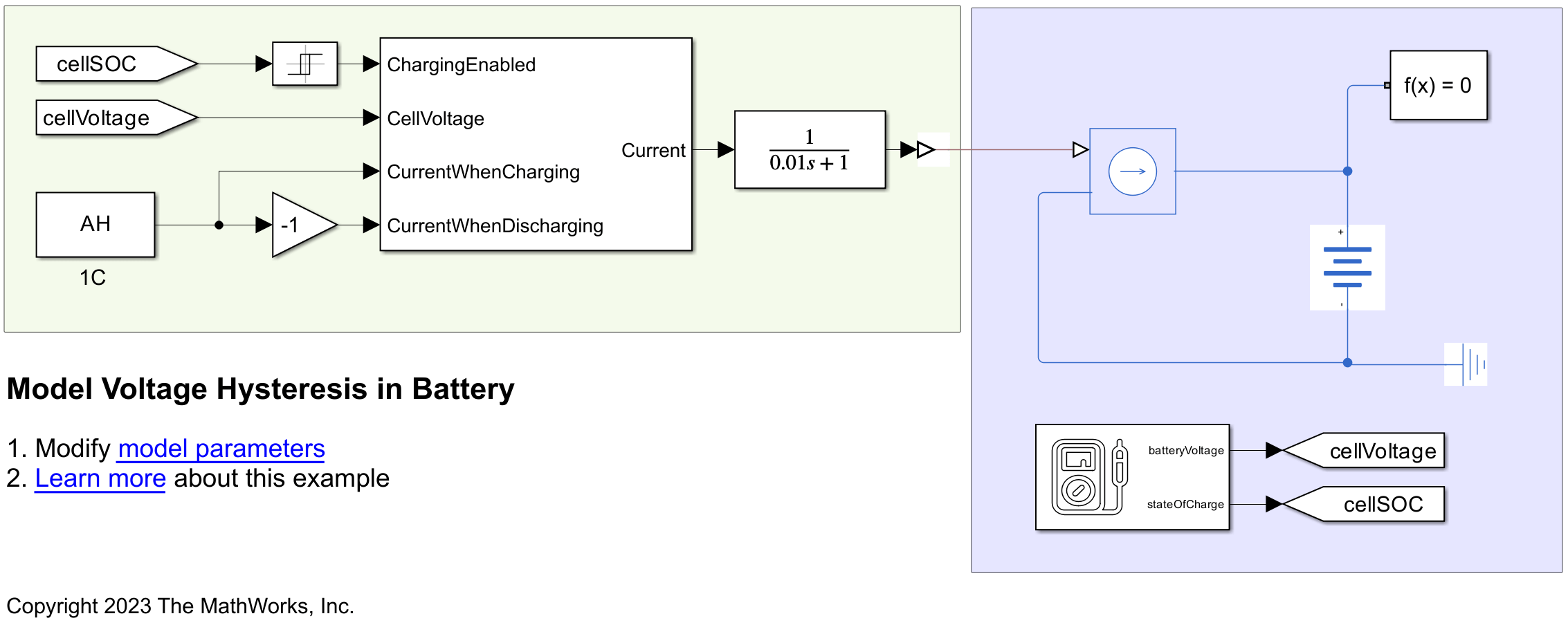
使用非活动滞后模型仿真电芯
如果滞后模型未激活,则 Battery Equivalent Circuit 模块在仿真期间使用开路电压,OCV (SOC) 参数的值。开路电压通常是充电和放电开路电压的平均值。为了提高仿真精度,您可以根据负载情况定义开路电压。要测量充电开路电压,通常会进行纯充电电势法试验,或采用恒电流间歇滴定法 (GITT)。在 GITT 期间,您将电池电芯充电至指定的荷电状态,然后让电池在零电流状态下静置一段时间。因此,OCV 电压仅在前一充电步骤完成并经过相应的电压放松时间后进行测量。相反,在仅放电试验中,您仅在放电步骤后测量放电开路电压。
如果您未选择有效的滞后模型,无论您是对电池电芯充电还是放电,OCV 始终保持不变。在没有滞后的情况下运行仿真,并绘制开路电压的行为。要设置仿真,请确保滞后模型未激活。
set_param([modelName,'/Cell'],'HysteresisModel','simscape.battery.enum.cells.HysteresisModel.none');
此外,滞后的初始条件也不得为活动状态。
set_param([modelName,'/Cell'],'hysteresisState_specify','off');
使用 1C 仿真完整的充电和放电循环。
hysteresisSimout = sim(modelName);
绘制结果。
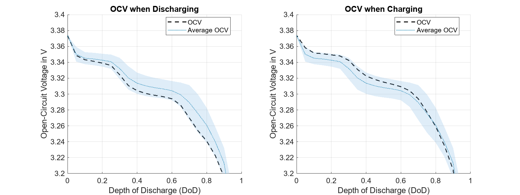
cellNoHysteresisPlot(hysteresisSimout,socVec,hysteresisChargeVoltage,hysteresisDischargeVoltage);

浅蓝色区域代表发生滞后的区域。表面的上下限分别代表充电 OCV 和放电 OCV。上限(红色虚线)为充电时的最大动态滞后电压。下限(黑色虚线)为放电时的最大动态滞后电压。黑线表示电池模型的 OCV,即充电和放电 OCV 的平均值。
虽然模型执行了完全充电和完全放电,但由于滞后模型未激活,电芯的 OCV 始终保持在同一条线上。根据所需的模型精度,使用平均 OCV 可能无法获得满意的结果。
使用活动滞后模型仿真电芯
现在,通过激活最简单的滞后模型来运行仿真。将 Battery Equivalent Circuit 模块的滞后模型参数设置为 oneStateModel。
set_param([modelName,'/Cell'],'HysteresisModel','simscape.battery.enum.cells.HysteresisModel.oneStateModel');
该滞后模型实现了电芯的 OCV 一阶模型。该模块使用以下方程式计算电芯的新 OCV:
,
其中 代表电芯滞后:
.
由于目前没有针对该电芯的热模型,因此最大动态滞后电压仅取决于 SOC。方程中的maximumDynamicHysteresisVoltage(SOC)项等于充电和放电 OCV 曲线之间的差值的一半:
.
hysteresisState 术语描述了电芯滞后的记忆效应。
-1 的
hysteresisState表示电芯模型使用的 OCV 从放电 OCV 曲线读取,该曲线由上图中的蓝色虚线表示。hysteresisState为 0 表示电芯模型使用的 OCV 从平均 OCV 读取。hysteresisState为 1 表示电芯模型使用的 OCV 从充电 OCV 曲线读取,该曲线在上一张图中用红色虚线表示。
hysteresisState 等于这个一阶特征方程,
,
其中 是当前电芯容量(以安培小时为单位), 是电芯电流,rateHysteresis 是决定 hysteresisState 值收敛速度的常数。rateHysteresis 越大,收敛速度就越快。
如果电芯正在充电,hysteresisState 的值将趋近于 1 和充电 OCV 曲线。如果电芯正在放电,hysteresisState 的值将趋近于 -1 和放电 OCV 曲线。如果电芯的电流为零,hysteresisState 将采用电芯在充电或放电时的最后值。
通过指定 hysteresisState 的初始值来分配滞后模型的初始条件。首先,将属性 hysteresisState_specify 设置为 on",以激活初始条件。
set_param([modelName,'/Cell'],'hysteresisState_specify','on');
在此示例中,hysteresisState 的初始值设置为 0。因此,电芯的初始 OCV 等于平均 OCV。
set_param([modelName,'/Cell'],'hysteresisState','0');
为了确保初始条件得到满足,将 hysteresisState_priority 属性设置为 High。
set_param([modelName,'/Cell'],'hysteresisState_priority','High');
将滞后率、HysteresisRate(SOC) 参数的值设置为 3。
simulationInput = Simulink.SimulationInput(modelName);
simulationInput = simulationInput.setVariable("rateHysteresis",3);通过将瞬时滞后电压,InstantaneousHysteresisVoltage(SOC) 参数设置为 0,禁用瞬时滞后电压。
simulationInput = simulationInput.setVariable("instantaneousHysteresisVoltage",zeros(21,1));使用 1C 进行满充放电循环,对模型进行仿真。
activeHysteresisSimout = sim(simulationInput);
绘制结果。
cellHysteresisPlot(activeHysteresisSimout,socVec,hysteresisChargeVoltage,hysteresisDischargeVoltage,ocvVec);
OCV 从蓝色虚线上的放电深度 (DOD) 为 0 处开始,该点为平均 OCV。在随后的放电阶段,OCV 向滞后电压放电曲线收敛。当接近 1 的值时,开始充电程序。由于电芯完全充电后,OCV 才达到充电滞后曲线,因此可以观察到 OCV 的滞后现象。
使用具有有源滞后模型和更高滞后率的电芯进行仿真
为了突出滞后率值对 OCV 的影响,将滞后率,HysteresisRate(SOC) 参数的值加倍。
simulationInput = simulationInput.setVariable("rateHysteresis",6);通过将瞬时滞后电压,InstantaneousHysteresisVoltage(SOC) 参数设置为 0,禁用瞬时滞后电压。
simulationInput = simulationInput.setVariable("instantaneousHysteresisVoltage",zeros(21,1));对模型进行仿真。
highHysteresisSimout = sim(simulationInput);
绘制结果。
cellHysteresisPlot(highHysteresisSimout,socVec,hysteresisChargeVoltage,hysteresisDischargeVoltage,ocvVec);

由于将滞后率加倍,放电和充电滞后曲线收敛得更快。
使用有滞后模型和瞬时滞后的电芯进行仿真
您可以通过添加瞬时滞后组件来扩展滞后模型。要指定瞬时滞后,请相应地设置瞬时滞后电压,InstantaneousHysteresisVoltage(SOC) 参数。如果为电池电芯启用了热模型,则设置瞬时滞后电压,InstantaneousHysteresisVoltageThermal(SOC,T) 参数。在此示例中,您将瞬时电压降设置为 10 mV,无论 SOC 值如何。对于非常低或非常高的 SOC 值,瞬时电压降为零:
simulationInput = simulationInput.setVariable("instantaneousHysteresisVoltage",[0;0;ones(17,1)*0.01;0;0]);为了计算滞后电压,Battery Equivalent Circuit 模块使用以下方程式:
.
instantaneousHysteresisVoltage(SOC) 项为滞后响应引入了一个瞬时组件。将 rateHysteresis 值设置回原始值 3。
simulationInput = simulationInput.setVariable("rateHysteresis",3);仿真模型,观察瞬态滞后组件的影响。
instantaneousHysteresisSimout = sim(simulationInput);
绘制结果。
cellHysteresisPlot(instantaneousHysteresisSimout,socVec,hysteresisChargeVoltage,hysteresisDischargeVoltage,ocvVec);

瞬时滞后电压比之前仿真中相对较慢的动态滞后发生得更快。请注意,各个动态和瞬时滞后因子的总和可能会超过最大动态滞后电压。
参考资料
Van der Ven, Anton, Kimberly A. See, and Laurent Pilon.2022.“Hysteresis in Electrochemical Systems”.Battery Energy 1 (2):Art. No. 20210017.
Plett, G. L. (2015).Battery Management Systems:Volume I, Battery Modeling.United Kingdom:Artech House.
F. Baronti, N. Femia, R. Saletti and W. Zamboni, "Comparing open-circuit voltage hysteresis models for lithium-iron-phosphate batteries" IECON 2014 - 40th Annual Conference of the IEEE Industrial Electronics Society, Dallas, TX, USA, 2014, pp. 5635-5640, doi:10.1109/IECON.2014.7049363.