Battery Equivalent Circuit

Libraries:
Simscape /
Battery /
Cells
Description
The Battery Equivalent Circuit block models the electro-thermal dynamics of a battery by using electrical circuit elements with variable characteristics and a zero-dimensional lumped-mass thermal heat equation. You can also use this block to simulate the faulted dynamics of a battery in shorted, open-circuit, and thermal runaway conditions. To model cycling aging and calendar aging of the battery, you can use lookup tables or empirical relationships. The block tabulates the variable characteristics of the electrical circuit elements as functions of the battery state of charge (SOC) and, optionally, current directionality, current, and temperature. This block comprises these constituent model files:
Electrical model
Open-circuit voltage and hysteresis model
Instantaneous overpotential model
Dynamic overpotential model
Thermal model
Constant
										temperature
Lumped thermal mass model
Cycling aging model
Equations
Temperature-independent table lookup
Temperature-dependent table lookup
Calendar aging model
Resistance aging model
Capacity aging model
Faults model
Short model
Open-circuit model
Exothermic reactions model
Electrical Model
The Battery Equivalent Circuit block models the battery terminal voltage by using a combination of electrical circuit elements arranged in a specific circuit topology. This figure shows the equivalent circuit topology, which relies on variable resistances, variable capacitances, and a variable voltage source. However, the implementation of the Battery Equivalent Circuit block is completely in the Simscape language.
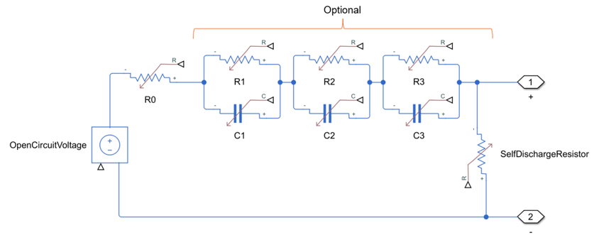
All the circuit elements have variable characteristics that are functions of other battery states:
OpenCircuitVoltage — The block tabulates this circuit element as a function of the SOC.
If you set the Thermal model parameter to
Constant temperature,Lumped thermal mass, orHeight distributed thermal mass, this circuit element also depends on the 2-D lookup temperature.If you set the Hysteresis model parameter to
One-state model, then the voltage source value is a function of the previous charge or discharge history of the battery.
R0, R1, R2, R3, Tau1, Tau2, Tau3 — The block tabulates this circuit element as a function of the SOC.
If you set the Thermal model parameter to
Constant temperature,Lumped thermal mass, orHeight distributed thermal mass, this circuit element also depends on the 2-D lookup temperature.If you set the Current dependence for resistance parameters parameter to
Lookup
											tables (current directionality dependent)
, then the resistance and capacitance values are also functions of the instantaneous current charge or discharge direction. Therefore, you can use charge and discharge parameter tables if they are available. If the current flowing through the battery is positive, then the block uses the charge lookup table parameters. If the current flowing through the battery is negative, then the block uses the discharge lookup table parameters.If you set the Current dependence for resistance parameters parameter to
Lookup
											tables (current dependent)
, then the resistance and capacitance values are also functions of the current. Therefore, you can use current parameter tables if they are available. (since R2025a)
SelfDischargeResistor — If you set the Thermal model parameter to
Constant temperature,Lumped thermal mass, orHeight distributed thermal mass, this circuit element also depends on the 2-D lookup temperature.
Note
For all the table-based parameters, the Battery Equivalent
Circuit block supports linear interpolation only. For
extrapolation, set the Extrapolation method for all tables
parameter to Nearest,
Linear, or Error.
For rows and columns, the extrapolation follows the row-column convention, in which rows are indexed before columns.
The Battery Equivalent Circuit calculates the terminal voltage of the battery at every time step by solving the Kirchhoff's voltage law
where:
U is the battery terminal voltage.
is the hysteresis-adjusted open-circuit voltage. The software updates the battery state of charge SOC, the temperature T, and the corresponding variables that depend on them at every time step during the simulation.
OCV(SOC,T) is the open-circuit voltage.
Uhyst(SOC,T) is the hysteresis voltage.
is the instantaneous overpotential. The software updates the battery SOC, the temperature, and the current directionality CurDir, as well as the corresponding variables that depend on them, at every time step during the simulation.
I is the battery current. If the value of I is positive, the block uses the charge lookup table parameters. If the value of I is negative, the block uses the discharge lookup table parameters.
is the dynamic overpotential. This optional term depends on the number of parallel resistor-capacitor pairs. This number can vary between 1 and 3. The software updates the battery SOC, temperature, and current directionality, as well as the corresponding variables that depend on them, at every time step during the simulation.
ΔURCi is the voltage drop for parallel resistor-capacitor pair i. The block calculates the voltage drop using this ordinary differential equation:
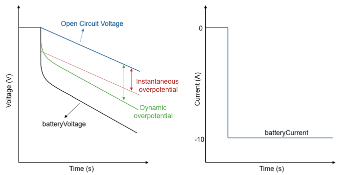
For the Battery Equivalent Circuit block, I has a negative sign during discharge and a positive sign during charge. During discharge, the block subtracts the battery overpotentials from the open-circuit voltage value, lowering the terminal voltage of the battery. In the discharge and charge cases, the overpotentials dissipate energy as heat. This figure shows the evolution of the battery overpotentials during a battery pulse discharge. The dynamic overpotential from the resistor-capacitor pairs increases slowly over the pulse, as opposed to the instantaneous overpotential, which increases during the first few milliseconds.
Batteries do not respond instantaneously to load changes. They require some time to achieve a steady state. This time-varying property is a result of the battery charge dynamics. The block models the charge dynamics by using parallel RC sections in the equivalent circuit.
To model the battery charge dynamics, set the Parallel resistor capacitor pairs parameter to one of these values:
No dynamics— The equivalent circuit contains no parallel RC sections. The battery exhibits no delay between terminal voltage and internal charging voltage.One time-constant dynamics— The equivalent circuit contains one parallel RC section.Two time-constant dynamics— The equivalent circuit contains two parallel RC sections.Three time-constant dynamics— The equivalent circuit contains three parallel RC sections.
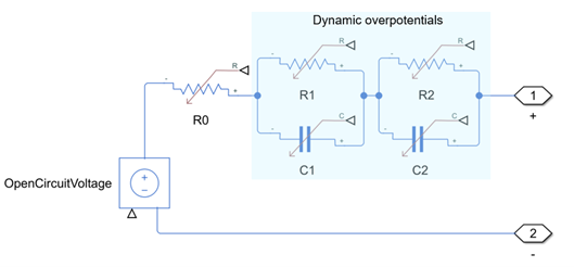
This diagram shows the battery equivalent circuit for the block circuit topology with only two time-constant dynamics and no self-discharge resistance.
In this figure:
R1 and R2 are the parallel RC resistances. Specify these values by setting the First polarization resistance, R1(SOC,T) and Second polarization resistance, R2(SOC,T) parameters, respectively, if you tabulate parameters over temperature. Otherwise, specify these values by setting the First polarization resistance, R1(SOC) and Second polarization resistance, R2(SOC) parameters, respectively. The voltage drop of the first RC pair is directly related to the activation overpotential from the chemical reaction at the interface of the electrodes. The time constant τ1 for this dynamic is typically lower than τ2, which indicates a faster response or faster dynamics. The voltage drop of the second RC pair is related to concentration overpotentials and typically evolves more slowly than the activation overpotential.
C1 and C2 are the parallel RC capacitances. The time constant τ for each parallel section relates the R and C values through the relationship . Specify τ for each section by using the First time constant, tau1(SOC,T) and Second time constant, tau2(SOC,T) parameters if you tabulate parameters over temperature or First time constant, tau1(SOC) and Second time constant, tau2(SOC) otherwise.
R0 is the instantaneous resistance. Specify this value with the Instantaneous resistance, R0(SOC,T) parameter if you tabulate parameters over temperature or Instantaneous resistance, R0(SOC) otherwise.
Note
The charge dynamics parameters can also depend on the current
directionality and on the current. If you set the Current
dependence for resistance parameters to Lookup
tables (current directionality dependent or
Lookup tables (current dependent), the
parameters in the Overpotential section change
accordingly.
The Battery Equivalent Circuit block calculates the SOC of the battery with the Coulomb counting method:
where:
Caged is the aged capacity of the cell.
ID,SD is the self-discharge current drain. This equation gives the current drain from the self-discharge resistor, which you can tabulate as a function of temperature T:
RSD(T) is the self-discharge resistance.
OCVinternal is the internal open-circuit voltage.
The Battery Equivalent Circuit block calculates the battery heat generation rate by adding these quantities:
Power dissipation terms from all the resistors in the equivalent circuit topology. This term is also called the irreversible heat generation. This quantity contains ohmic and activation overpotential heat terms.
Reversible heat generation from entropy
Heat generation terms from the faulted cell behaviour:
Short resistance (or parallel-added resistance)
Open-circuit resistance (or series-added resistance)
Thermal runaway reaction heat
This equation shows this summation:
where:
is the heat generation rate.
is the dissipated power.
RSD is characterized under an open-circuit condition. In this condition, the battery terminal voltage is equal to the internal open-circuit voltage.
Qflow,series is the series resistor heat flow.
Qflow,parallel is the parallel resistor heat flow.
The block only takes Qflow,series and Qflow,parallel into account in fault scenarios. For more information, see Model Faults.
is the reversible heat.
Qflow,exr is the exothermic reaction heat flow. For more information, see Model Faults.
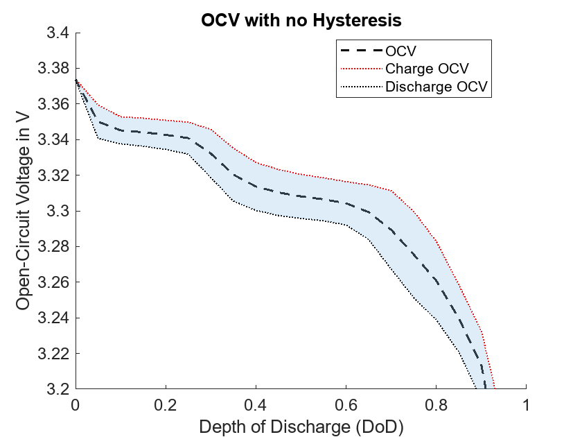
The hysteresis of a battery describes the dependency of the open-circuit voltage (OCV) on the charge or discharge history. Hysteresis is only indirectly dependent on the OCV.
The data obtained from measuring the OCV during a complete charging or discharging cycle is called a major loop. If the battery is only partially charged or discharged, the measured OCV forms a minor loop. The minor loops approach the major loops after a delay in charge. This effect is prominent in Li-ion batteries and it has a significant effect on the SOC estimation.
The Battery Equivalent Circuit block models the hysteresis by using a one-state model
where:
Uhyst is the hysteresis voltage.
H defines the hysteresis state. The block uses this ordinary differential equation to calculate the hysteresis state:
γ is the hysteresis rate.
Caged is the aged capacity of the cell.
M is the value of the Maximum dynamic hysteresis voltage, MaximumHysteresisVoltageThermal(SOC,T) parameter if you tabulate the parameters over temperature, or Maximum dynamic hysteresis voltage, MaximumHysteresisVoltage(SOC) otherwise.
M0 is the value of the Instantaneous hysteresis voltage, InstantaneousHysteresisVoltageThermal(SOC,T) parameter if you tabulate the parameters over temperature, or Instantaneous hysteresis voltage, InstantaneousHysteresisVoltage(SOC) otherwise.
For more information on hysteresis and on how to model it, see the Model Voltage Hysteresis in Battery example.
When the battery terminals are open-circuit, internal currents can still
discharge the battery. This behavior is called self-discharge. To enable and
model this effect, set the Self discharge parameter to
Enabled.
The block models these internal currents with a temperature-dependent resistance RSD(T) across the terminals of the fundamental battery model. Specify the lookup values for this resistance by using the Self-discharge resistance, SelfDischargeR(T) parameter if you tabulate the parameters over temperature, or Self-discharge resistance, SelfDischargeR otherwise.
Thermal Model
Setting the Thermal model parameter to Lumped
thermal mass adds a thermal model to the Battery
Equivalent Circuit block. This model computes the battery
temperature at every time step. The block uses this temperature for all
temperature-dependent lookup tables. The lumped thermal mass adds this ordinary
differential equation:
where:
Mth is the battery thermal mass.
is the heat across the H thermal port.
To increase the fidelity of the thermal
modeling and to model the thermal gradient inside the block, you can discretize the
thermal model along the cell height. To height-discretize the thermal model, set the
Thermal model parameter to Height distributed
thermal mass. The block then exposes the
HDist thermal port, which is an array of thermal nodes that
represents the nodes along the height of the cell. To compute the electrical
behavior of the cell, the block uses the mean of the discretized thermal
nodes. (since R2024b)
Cycling Aging Model
Battery aging is the deterioration of the battery performance over repeated charge and discharge cycles.
This block allows you to model the battery aging by setting the Cycling aging model parameter to one of these options:
Disabled— Do not model fading characteristic.Equations— The cell capacity and terminal resistance are proportional to . The open-circuit voltage is proportional to N. If you enable the self-discharge resistance or any of the time constants, their values are proportional to .Lookup tables (temperature independent)— Lookup table of the percent change of the underlying parameter, as a function of the number of discharge cycles, N.Lookup tables (constant temperature dependent)— Lookup table of percent change of the underlying parameter, as a function of the number of discharge cycles and the present battery temperature. Use this option only if your battery operates at a near-constant temperature. For batteries with varying temperatures, useLookup tables (temperature dependent)orLookup tables (temperature and current dependent).Lookup tables (temperature dependent)— Lookup table of the percent change of the underlying parameter, as a function of the number of discharge cycles and the present battery temperature. Due to how the block internally calculates the value of the underlying parameter at the next timestep, this tabulated data must be strictly monotonically increasing or decreasing with respect to the number of discharge cycles. Use this option if your battery operates at variable temperatures. For batteries at near-constant temperatures, useLookup tables (constant temperature dependent)to achieve better simulation performance. (since R2025a)Lookup tables (temperature and current dependent)— Lookup table of the percent change of the underlying parameter, as a function of the number of discharge cycles, the present battery temperature, and the present cell current. Due to how the block internally calculates the value of the underlying parameter at the next timestep, this tabulated data must be strictly monotonically increasing or decreasing with respect to the number of discharge cycles. Use this option if your battery operates at variable temperatures. (since R2025a)
For more information about cycling aging and the equations used in this block, see [4], [5], [9], [11], and [12].
When you set the Cycling aging model parameter to
Equations, the open-circuit voltage across the
fundamental battery model fades proportionally with the number of discharge cycles
n:
where δOCV(N,T) is the percentage change in open-circuit voltage after N discharge cycles. Specify δOCV(N,T) by using the Change in open-circuit voltage after NumDisCycles discharge cycles (%) parameter.
Note
The Battery Equivalent Circuit block tracks the current and integrates it over time. The number of discharge cycles n depends on the value of the Cycle calculation method parameter:
Equivalent cycles— The block uses the aged capacity to calculate the number of discharge cycles.Equivalent full cycles— The block uses the value of the Battery capacity parameter to calculate the number of discharge cycles
The nominal charge, from which the block calculates the SOC, fades with the square root of the number of discharge cycles:
where C is the initial capacity and δC(N,T) is the percentage change in capacity after N discharge cycles. Specify δC(N,T) by using the Change in capacity after NumDisCycles discharge cycles (%) parameter.
All resistances in the battery model also fade with the square root of the number of discharge cycles:
where δRi(N,T) is the percentage change in the ith resistance after N discharge cycles. Specify δRi(N,T) by using the Change in resistance after NumDisCycles discharge cycles (%) parameter.
Depending on how you configure the block, the resistances include these values:
Instantaneous resistance — Specify the percentage change over NumDisCycles cycles using the Change in instantaneous resistance after NumDisCycles discharge cycles (%) parameter.
Self-discharge resistance — Specify the percentage change over NumDisCycles cycles using the Change in self-discharge resistance after NumDisCycles discharge cycles (%) parameter.
First charge dynamics resistance — Specify the percentage change over NumDisCycles cycles using the Change in first polarization resistance after NumDisCycles discharge cycles (%) parameter.
Second charge dynamics resistance — Specify the percentage change over NumDisCycles cycles using the Change in second polarization resistance after NumDisCycles discharge cycles (%) parameter.
Third charge dynamics resistance — Specify the percentage change over NumDisCycles cycles using the Change in third polarization resistance after NumDisCycles discharge cycles (%) parameter.
Note
You can also model the battery cycling aging characteristic by using the temperature-dependent, temperature-independent, or temperature-and-current-dependent lookup tables. Choosing one of these options changes the block parameters accordingly.
Calendar Aging Model
You can model the battery performance deterioration that occurs when the battery is not in use. Calendar aging affects the internal resistance and the capacity. In particular, the resistance increase varies by mechanisms such as the creation of a solid-electrolyte interface (SEI) at the anode and cathode and the corrosion of the current collector. These processes mainly depend on the storage temperature, the storage SOC, and storage time.
To model calendar aging in the Battery Equivalent Circuit block,
set one of the Resistance calendar aging or Capacity
calendar aging parameters to Enabled and
then set the Modeling option parameter to one of these values:
Equation-basedTabulated: temperatureTabulated: time and temperature
Note
The Battery Equivalent Circuit block applies the calendar aging
only during initialization. When you set the Resistance calendar
aging or Capacity calendar aging parameter
to Enabled, the block exposes the Vector of
time intervals parameter, which represents the time over which
the battery ages before the start of the simulation. This option does not
include calendar aging during the simulation.
For more information about calendar aging and the equations used in this block, see [9] and [12].
These equations define the terminal resistance increase of the battery due to calendar aging:
where:
Voc is the Normalized open-circuit voltage during storage, V/Vnom parameter.
R0 is the Internal resistance parameter.
ti is the time sample derived from the Vector of time intervals parameter.
Ti is derived from the Temperature breakpoints, T parameter.
bR is the Terminal resistance linear scaling for voltage, b parameter.
cR is the Terminal resistance constant offset for voltage, c parameter.
dR is the Terminal resistance temperature-dependent exponential increase, d parameter.
aR is the Terminal resistance time exponent, a parameter.
q is the electron elementary charge, in C.
k is the Boltzmann constant, in J/K.
These equations define the capacity decrease of the battery due to calendar aging:
where:
C is the initial capacity.
bC is the Capacity linear scaling for voltage, b parameter.
cC is the Capacity constant offset for voltage, c parameter.
dC is the Capacity temperature-dependent exponential increase, d parameter.
aC is the Capacity time constant, a parameter.
If you set the Storage condition parameter to
Specify state-of-charge during storage, the block
converts the SOC during storage into the normalized open-circuit voltage by
using the tabulated voltage V0
against the SOC and the temperature during storage.
The aged terminal resistance is the product of the terminal resistance, R0(SOC,T), the percentage resistance increase, dR0, and the power law that describes the time dependence of the calendar aging:
where:
T is the battery temperature. Specify the T breakpoints using the Temperature breakpoints, T parameter if you tabulate the parameters over temperature.
Tst is the Vector of storage temperatures parameter.
tst,i and tst,i-1 are the time samples derived from the Vector of time intervals parameter.
t0 is 0.
tst,m is the moment at which the software measures the resistance increase, dR0.
The same equation applies to the calculation of the aged battery capacity.
The aged terminal resistance is the product of the terminal resistance, R0(SOC,T) and dR0:
The same equation applies to the calculation of the aged battery capacity.
Model Faults
To model a fault in the Battery Equivalent Circuit block, in the Faults section, click Add fault next to the fault that you want to model. For more information about fault modeling, see Fault Behavior Modeling and Fault Triggering.
The Battery Equivalent Circuit block supports three different types of fault:
Additional resistance fault — The resistance of a series-connected resistor ranges from a value of 0 ohm to a value that you specify. You can use this fault to model an open-circuit cell when the additional series-connected resistance is high (greater than 1000 ohm), or an abnormal internal resistance.
Internal short fault — The resistance of a parallel-connected resistor ranges from an infinite value to a value that you specify.

Exothermic reactions — Use this fault to simulate a thermal runaway event. Heat-releasing chemical reactions occur at the cell level. At low temperatures, the rate of reaction is low and the self-heating rate is not significant. At higher temperatures, the rate of exothermic reactions increases exponentially. The battery generates more heat than the amount it can dissipate. The temperature starts to rise exponentially, reaches a thermal runaway event, and the cell starts to burn. During the burn, the cell electrical behavior is equivalent to an open circuit.

The released heat rate is a function of the extent of the reaction and the cell temperature:
where:
Kscale is a constant that scales the equation to define how fast the reaction advances.
ξ is the reaction extent. If the reaction extent is 0, the reaction has not started. If the reaction extent is 1, the reaction has consumed all possible reactants and is completed.
ρ is the value of the Order of reaction parameter and defines the polynomial dependency of the reaction rate with respect to the extent of reaction.
is the Arrhenius equation and defines the temperature dependency. Ea is the activation energy, in kJ/mol, and R is equal to 8.314 J/k/mol.
The block computes Kscale by using the Exotherm onset temperature parameter. The exotherm onset temperature is the temperature in an accelerating rate calorimetry (ARC) test at which the self-heating rate exceeds a threshold of 0.02 celsius per minute at which the reaction heat rate slowly increases the cell temperature. If the temperature exceeds this value, the reaction becomes self-sustaining and eventually produces the runaway event.
In an ARC test, the released heat rate at the exothermic onset is equal to:
where:
TEO is the exothermic onset temperature in Kelvin.
Mth,cell is the thermal mass of the cell.
dTdtEO is the rate of change of the cell temperature when the cell is at the exothermic onset temperature. The typical value is 0.02 celsius per minute.
You can then compute Kscale as a function of dTdtEO, TEO, the thermal mass of the cell, and the activation energy:
As the reaction advances, some of the materials in the battery decompose into gases. These gases dissipate into the environment. The loss of these materials decreases the thermal mass of the battery. To model this loss of thermal mass, the thermal mass decreases linearly with the reaction extent. To control the rate of thermal mass decrease with reaction extent, specify the Percent of thermal mass vented parameter accordingly.
You specify how and when faults occur by using the Trigger Type parameter.
If you set the Trigger Type parameter to
Timed, the Battery Equivalent Circuit block triggers fault
events when the simulation time reaches the value you specify for the
Trigger fault at time parameter.
For the exothermic reactions fault, if you set the Trigger
Type to Behavioral, the Battery Equivalent Circuit
block triggers fault events when the temperature exceeds the value of the
Trigger temperature parameter.
If you set the Trigger
Type to Conditional, you can choose whether faults
in the Battery Equivalent Circuit block are reversible (since R2025a). To model irreversible faults, click
Open fault properties to open the Property Inspector and select the
Trigger stays on once activated parameter. The block enters the faulted
state when the trigger condition becomes true for the first time and remains in the faulted
state for the rest of the simulation. To model reversible faults, clear the Trigger
stays on once activated parameter. The block enters the faulted state when the
trigger condition is true and enters the unfaulted state when the trigger condition is
false.
Note
Exothermic reactions fault and internal short fault do not support reversible faults.
For more information about adding faults to blocks and specifying fault triggers, see Introduction to Simscape Faults.
Part Collection
You can parameterize the Battery Equivalent Circuit block by using parts in the Simscape Battery part collection that represent components from specific suppliers.
These parts model the steady-state electrical parameters of a battery. The parts define the Open-circuit voltage (SOC), Instantaneous resistance, R0(SOC, T), Battery capacity, Percentage change in cell capacity, CapacityChange(N), and Percentage change in open-circuit voltage, OCVChangeVec(N) parameters from characteristic curves in the manufacturer data sheets. The parts do not parameterize the change in series resistance with the battery cycle life and the dynamic RC network parameters. Instead, each part sums the net resistance of the RC network resistors to the series resistance of the specific parameterized data. To populate the RC parameter data, subtract the net RC network resistance from the series resistance data. The software estimates the battery thermal mass by assuming a value of 900 J/kg K for the specific heat of the battery. The thermal mass is then equal to 900 times the weight of the battery in the manufacturer data sheet.
The available data corresponds to a 1 C discharge current for different temperatures up to the minimum terminal voltage in the data sheet. The software extrapolates the data below the minimum terminal voltage. The Open-circuit voltage, OCV(SOC) parameter is temperature-independent. At lower temperatures, in the low-SOC region, the terminal resistances are constant and equal to the value of the resistance at the minimum terminal voltage. In this regime, batteries often experience higher thermal losses.
For a list of the available components, see Simscape Electrical Part Collection (Simscape Electrical).
Generate Derived Data Sheet
Since R2025a
You can generate a derived data sheet for the Battery Equivalent Circuit block that contains summary tables and characteristic plots similar to those that device manufacturers provide in their data sheets. A built-in MATLAB® script calculates the block-level characteristics based on the parameter values in your model. Use derived data sheets to explore the impact of your parameter choices on device characteristics, help you select manufactured parts, or share your component-level design with other members of your organization.
The derived data sheet for the Battery Equivalent Circuit block, includes charging, discharging, cycle life, shelf life, and hysteresis characteristics.
To generate a derived data sheet:
Open the MATLAB script by clicking the Open live script button next to the Derived data sheet parameter in the Utilities section of the block dialog box.
Click the Generate Data Sheet button in the script.
Before R2026a: To open the MATLAB script, you double-click the block to open the Block Parameters window, open the Description tab, and click the Generate Datasheet hyperlink.
Variables
To set the priority and initial target values for the block variables before simulation, use the Initial Targets section in the block dialog box or Property Inspector. For more information, see Set Priority and Initial Target for Block Variables.
Nominal values provide a way to specify the expected magnitude of a variable in a model. Using system scaling based on nominal values increases the simulation robustness. You can specify nominal values using different sources, including the Nominal Values section in the block dialog box or Property Inspector. For more information, see System Scaling by Nominal Values.
Public Variables (Visible with Probe Block)
The Battery Equivalent Circuit block comprises these public variables that you can probe using the Probe block:
batteryCurrent— Total current measured through the battery terminals. By default, this variable has units of Amperes.batteryTemperature— Battery average temperature that the block uses for the table look-up of resistances and open-circuit voltage. If you set the Thermal model parameter toConstant temperature, then thebatteryTemperaturevariable is equal to the specified temperature value. If you set the Thermal model parameter toLumped thermal mass, then thebatteryTemperaturevariable is a differential state that varies during the simulation.batteryVoltage— Battery terminal voltage, or the voltage difference between the positive and the negative terminals. By default, this variable has units of Volts.capacityCyclingChange— Percentage change of the battery capacity after the specified discharge cycles. By default, this variable is unitless.charge— Electrical charge drawn from or added to the battery. By default, this variable has units of A*h.heatGenerationRate— Total battery heat generation rate. The block calculates the heat generation rate by adding up all resistive losses, reversible heating contribution, and the exothermic reaction heat if you enabled an exothermic fault. By default, this variable has units of Watts.hysteresisState— Hysteresis state in the range [-1,1]. A value of 1 indicates that the block is using the charge open-circuit voltage curve at that time step. A value of -1 indicates that the block is using the discharge open-circuit voltage curve at that time step. By default, this variable is unitless.isCurrentInterruptionTempExceeded— Boolean that indicates whether the battery has exceeded its current interruption temperature during a thermal runaway event. This variable is relevant only when modeling faults.isExothermFaulted— Boolean that indicates whether the battery model has transitioned into a thermal runaway or exothermic mode. This mode can be triggered by high temperature or timed based on the fault model specification. This variable is relevant only when modeling faults.numCycles— Equivalent number of discharge cycles of the battery. The counter starts at zero and increases by one every time an equivalent discharge charge has been drawn from the battery. By default, this variable is unitless.ocv— Open-circuit voltage of the battery adjusted for temperature, ageing, and state of charge. By default, this variable has units of Volts.power_dissipated— Resistive heat generation rate or dissipated power. By default, this variable has units of Watts.r0CyclingChange— Percentage change of the battery instantaneous resistance after the specified discharge cycles. By default, this variable is unitless.r1CyclingChange— Percentage change of the first polarization resistance of the battery after the specified discharge cycles. By default, this variable is unitless.r2CyclingChange— Percentage change of the second polarization resistance of the battery after the specified discharge cycles. By default, this variable is unitless.r3CyclingChange— Percentage change of the third polarization resistance of the battery after the specified discharge cycles. By default, this variable is unitless.reactionExtent— Exothermic reaction progression in the range [0,1]. Initially, the value of this variable is 0. This variable is relevant only when modeling faults.reactionHeatRate— Exothermic reaction heat, if you enabled an exothermic fault. By default, this variable has units of Watts.reversibleHeat— Reversible heating contribution from entropy changes. By default, this variable has units of Watts.selfDischargeRCyclingChange— Percentage change of the self-discharge resistance of the battery after the specified discharge cycles. By default, this variable is unitless.stateOfCharge— Battery state of charge obtained from coulomb counting. By default, this variable is unitless.voltageDropRC1— Voltage drop that the first RC branch of the equivalent circuit model causes. By default, this variable has units of Volts.voltageDropRC2— Voltage drop that the second RC branch of the equivalent circuit model causes. By default, this variable has units of Volts.voltageDropRC3— Voltage drop that the third RC branch of the equivalent circuit model causes. By default, this variable has units of Volts.
Examples

Characterize Cell Thermal Runaway with Accelerating Rate Calorimetry (ARC) Test
Characterize the thermal runaway behavior of a battery cell by simulating an accelerating rate calorimetry (ARC) test.

Parameterize Entropic Coefficient with Measurement Protocol and Data Analysis
What experiments to conduct and how to analyze the resulting experimental data for parameterizing the entropic coefficient. The entropic heat is a reversible heat generation term inside battery thermal models. This equation calculates the entropic heat,
Model Voltage Hysteresis in Battery
Simulate the voltage hysteresis phenomena in rechargeable batteries by using the Battery Equivalent Circuit block. The open-circuit voltage (OCV) is the difference in measured voltage between the battery terminals when the current flow is equal to zero. The OCV is the electromotive force or the rest potential. For rechargeable or secondary batteries such as lithium-ion batteries, the OCV at a given state of charge and temperature state depends on whether you previously charged or discharged the battery. In lithium-ion cells with conventional intercalation electrodes, this discrepancy is typically explained by the presence of different solid phases in the electrode active material, reaction path hysteresis, and related thermodynamic effects. The lithiation and delithiation of an electrode active material during the charge and discharge processes often produce different electrode solid phases at different states of charge depending on battery chemistry.

Model Battery Cycling Aging
Simulate the capacity cycling aging of a battery. Battery aging is a critical factor that affects the performance and lifespan of energy storage systems. As batteries undergo charge and discharge cycles, their components degrade, which leads to a gradual decline in capacity and efficiency. Solid electrolyte interface (SEI), lithium plating, and other side reactions are the main cause of degradation in lithium-ion batteries.
Ports
Conserving
Parameters
References
[1] Zhang, Ran, and Zhengqiang Pan. “Model Identification of Lithium-Ion Batteries Considering Current-Rate Effects on Battery Impedance.” In 2019 4th International Conference on Power and Renewable Energy (ICPRE), 305–9. Chengdu, China: IEEE, 2019. https://doi.org/10.1109/ICPRE48497.2019.9034704R.
[2] Baronti, Federico, Nicola Femia, Roberto Saletti, Ciro Visone, and Walter Zamboni. “Hysteresis Modeling in Li-Ion Batteries.” IEEE Transactions on Magnetics 50, no. 11 (November 2014): 1–4. https://doi.org/10.1109/TMAG.2014.2323426
[3] Baronti, F., W. Zamboni, N. Femia, R. Roncella, and R. Saletti. “Experimental Analysis of Open-Circuit Voltage Hysteresis in Lithium-Iron-Phosphate Batteries.” In IECON 2013 - 39th Annual Conference of the IEEE Industrial Electronics Society, 6728–33, 2013. https://doi.org/10.1109/IECON.2013.6700246
[4] Ramadass, P., Bala Haran, Ralph White, and Branko N. Popov. “Mathematical Modeling of the Capacity Fade of Li-Ion Cells.” Journal of Power Sources 123, no. 2 (September 2003): 230–40. https://doi.org/10.1016/S0378-7753(03)00531-7
[5] Ning, Gang, Bala Haran, and Branko N. Popov. “Capacity Fade Study of Lithium-Ion Batteries Cycled at High Discharge Rates.” Journal of Power Sources 117, no. 1–2 (May 2003): 160–69. https://doi.org/10.1016/S0378-7753(03)00029-6
[6] Plett, Gregory L. Battery Management Systems. Volume I, Battery Modeling. Artech House, 2015.
[7] Guangming Liu, et al. "A Comparative Study of Equivalent Circuit Models and Enhanced Equivalent Circuit Models of Lithium-Ion Batteries with Different Model Structures". 2014 IEEE Conference and Expo Transportation Electrification Asia-Pacific (ITEC Asia-Pacific), IEEE, 2014, pp. 1–6. DOI.org (Crossref), https://doi.org/10.1109/ITEC-AP.2014.6940946.
[8] Lee, SoDuk, et al. Modeling and Validation of 12V Lead-Acid Battery for Stop-Start Technology. 2017, pp. 2017-01–1211. DOI.org (Crossref), https://doi.org/10.4271/2017-01-1211.
[9] Yi Li, Kailong Liu, Aoife M. Foley, Alana Zülke, Maitane Berecibar, Elise Nanini-Maury, Joeri Van Mierlo, Harry E. Hoster. "Data-driven health estimation and lifetime prediction of lithium-ion batteries: A review". Renewable and Sustainable Energy Reviews 113, 2019, ISSN 1364-0321, https://doi.org/10.1016/j.rser.2019.109254.
[10] Roy, Probir Kumar, Mohammad Shahjalal, Tamanna Shams, Ashley Fly, Stoyan Stoyanov, Mominul Ahsan, and Julfikar Haider. 2023. "A Critical Review on Battery Aging and State Estimation Technologies of Lithium-Ion Batteries: Prospects and Issues" Electronics 12, no. 19: 4105. https://doi.org/10.3390/electronics12194105
[11] Perez, HE, Hu, X, Dey, S & Moura, SJ 2017, 'Optimal Charging of Li-Ion Batteries with Coupled Electro-Thermal-Aging Dynamics', IEEE Transactions on Vehicular Technology, vol. 66, no. 9, 7867072, pp. 7761-7770. https://doi.org/10.1109/TVT.2017.2676044
[12] Schimpe, M., et al. "Comprehensive Modeling of Temperature-Dependent Degradation Mechanisms in Lithium Iron Phosphate Batteries". Journal of The Electrochemical Society, vol. 165, no. 2, 2018, pp. A181–93. DOI.org (Crossref) , https://doi.org/10.1149/2.1181714jes. CloseDeleteEdit
Extended Capabilities
Version History
Introduced in R2023bSee Also
Topics
- Characterize Powertrain Blockset and Simscape Battery Blocks (App) (Model-Based Calibration Toolbox)
- Simscape Electrical Part Collection (Simscape Electrical)