Slider-Crank (AB-PB)
R2026bSlider-Crank (AB-PB) block

To add a block to a model, double-click the canvas and start typing the block name. Then, select the block from the list.
Libraries:
Simscape /
Foundation Library /
Mechanisms
Description
The Slider-Crank (AB-PB) block represents an ideal slider-crank mechanism that converts between the continuous rotational motion of the crank and the oscillating translational motion of the slider.
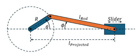
The block uses the equations
where:
R is the crank radius.
lRod is the rod length.
lProjected is the distance between the crank axle and the slider.
θ is the crank angle relative to top dead center. When θ is 0, the slider-crank mechanism is at maximum projected length.
Φ is the rod obliquity angle.
t is the torque of the rotational network acting on the crank axle. Positive torque drives the crank in the positive rotational direction.
f is the force of port Bt acting on port Ft.
fSide is the side force, that is, the normal force between the slider and the rail that it slides on.
The angle-based rotational ports Br and Fr are rigidly connected to each other and represent the crank axle. The position-based translational ports Bt and Ft represent the axle and the slider. Use the Translational port for slider (graphical) parameter to specify which of these ports corresponds to the slider.
To model friction effects on the slider, select Enable side force output and connect the Fs port to port N of a Translational Friction (PB) block.
The block does not model crank inertia, slider stiffness, or slider damping. To avoid computational issues:
To help the mechanism maintain momentum as it passes through top dead center and bottom dead center, attach an Inertia (AB) block to the crank axle.
To avoid numerical instability, attach a Rotational Damper (AB) block to the crank axle.
When driving the system with a torque source, attach a rotational load, such as inertia or damper, to the torque source, as well as to the Slider-Crank (AB-PB) block, because the slider-crank does not absorb torque at top dead center (θ = 0 deg) and bottom dead center (θ = 180 deg).
When driving the system with a torque source, initialize the crank at an angle other than 0 deg or 180 deg, so that the system can apply a force to the slider.
Variables
To set the priority and initial target values for the block variables prior to simulation, use the Initial Targets section in the block dialog box or Property Inspector. For more information, see Set Priority and Initial Target for Block Variables.
Nominal values provide a way to specify the expected magnitude of a variable in a model. Using system scaling based on nominal values increases the simulation robustness. Nominal values can come from different sources, one of which is the Nominal Values section in the block dialog box or Property Inspector. For more information, see Modify Nominal Values for a Block Variable.
Examples
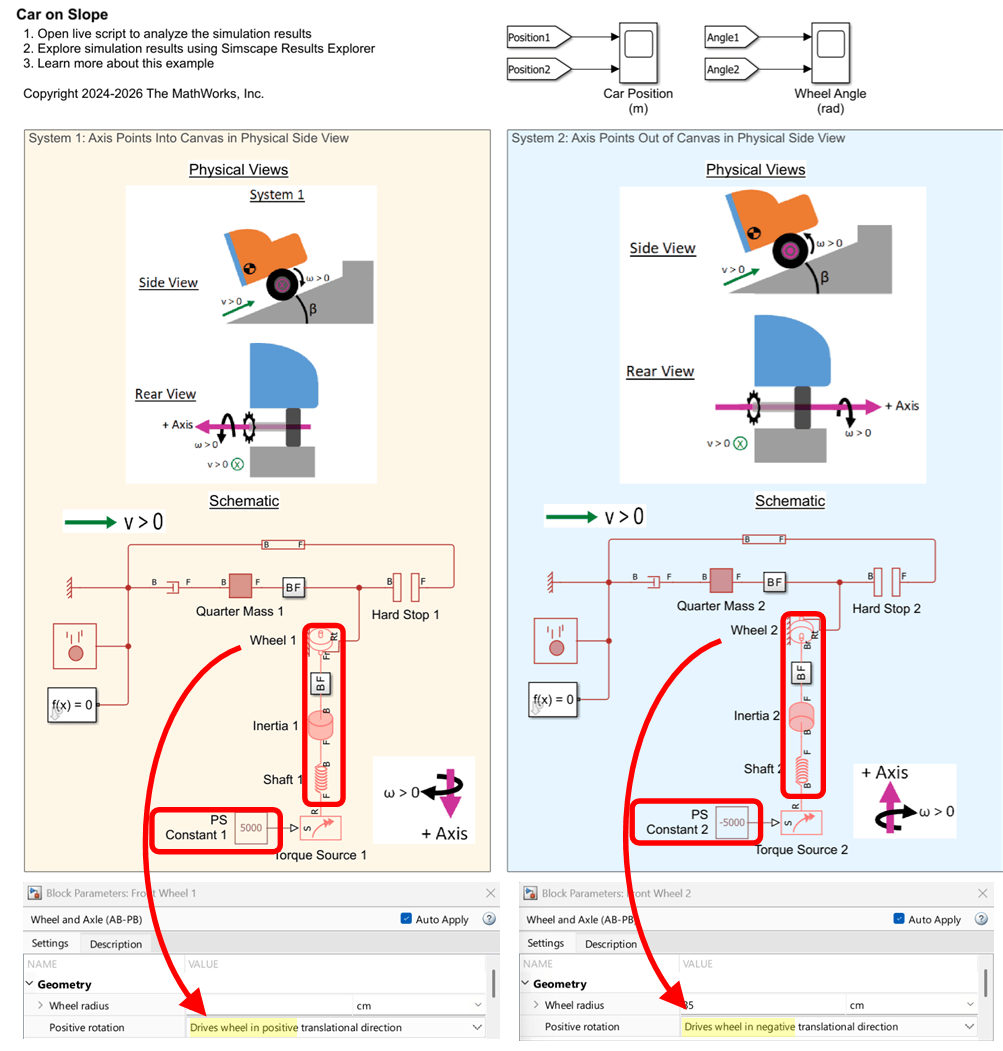
Interfacing Angle-Based Rotational and Position-Based Translational Networks
Demonstrates how you can define positive directions for translation and rotation in your physical view and adjust the Simscape™ network to achieve the desired behavior. It highlights the flexibility of Simscape in mapping physical directions to schematic representations.
Ports
Conserving
Output
Parameters
Geometry
Radius of the crank.
Programmatic Use
Parameter:
crank_radius
Length of the rod connecting the crank and the slider. The parameter value must be greater than the value of the Crank radius parameter.
Programmatic Use
Parameter:
rod_length
Ports
To improve block diagram readability, specify the rotational ports to display. The two rotational ports are rigidly attached to each other, so the effect is purely graphical and the block functions exactly the same whether it has one or two ports. Select the rotational ports visible on the block icon:
Br and Fr— Expose both ports, Br and Fr.Br— Expose only port Br.Fr— Expose only port Fr.
Programmatic Use
| Parameter: | visible_rotational_ports |
| Values: | "foundation.enum.MechanismRotationalPorts.Br" | "foundation.enum.MechanismRotationalPorts.Fr" | "foundation.enum.MechanismRotationalPorts.BrFr" |
To improve block diagram readability, specify which of the translational ports corresponds to the slider. The effect is purely graphical. Select the translational port to use:
Ft— Attach port Ft to the slider.
Bt— Attach port Bt to the slider.
Programmatic Use
| Parameter: | slider_port |
| Values: | "foundation.enum.MechanismTranslationalPort.Ft" | "foundation.enum.MechanismTranslationalPort.Bt" |
Select this check box to enable the physical signal output port Fs, which outputs the side force between the slider and its rail. Use this signal to model the friction effects on the slider.
Programmatic Use
| Parameter: | enable_side_force_port |
| Values: | "true" | "false" |
Extended Capabilities
Version History
Introduced in R2026b

