Initialize, Reset, and Terminate State of Simulink Block
This example shows how to use the Initialize Function block and Reset Function block to initialize and reset the Discrete-Time Integrator block states and how to use the Terminate Function block to terminate the integration process based on an event schedule.
Model Using Initialize Function, Reset Function, and Terminate Function Block
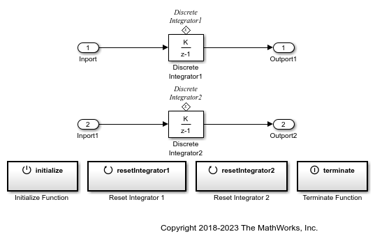
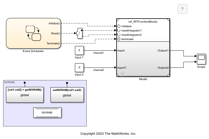
The ref_IRTFunctionBlocks model uses one Initialize Function block, two Reset Function blocks, and one Terminate Function block. The two Reset Function blocks reset the two Discrete-Time Integrator block states.
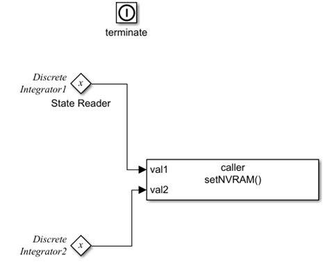
In this example, the State Writer blocks inside the Initialize and Reset Function blocks set the states of the Discrete-Time Integrator blocks. The State Reader block inside the Terminate Function block reads the states of the Discrete-Time Integrator blocks. For more information about the blocks that allow State Writer and State Reader blocks, see State Writer and State Reader.
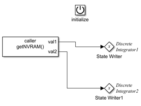
The Initialize Function block uses the State Writer block to set the Discrete-Time Integrator block states when the Initialize Function block receives an initialize function-call event.
The Reset Function block uses the State Writer block to reset the Discrete-Time Integrator block states when the Reset Function blocks receive the reset function-call events.
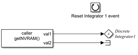
Two Reset Function blocks are used at the root level of the ref_IRTFunctionBlocks model. When using multiple Reset Function blocks at the same model hierarchy level, you must use unique event names for the Event name parameter of the Event Listener blocks for those Reset Function blocks. In this model, Event name is resetIntegrator1 for the Reset Integrator 1 block, and resetIntegrator2 for the Reset Integrator 2 block.

The Terminate Function block terminates the integration when the block receives a terminate function-call event.
For more information, see Using Initialize, Reinitialize, Reset, and Terminate Functions.
Model Behavior
The model is simulated based on function-call events and uses the Discrete-Time Integrator block state values from the data store.
The
ref_IRTFunctionBlocksmodel is referenced by a Model block at the root level of theex_IRTFunctionBlocksmodel.The event scheduler is modeled using Stateflow® charts that generate function-call events. The model executes based on the function-call events.
Discrete Integrator1andDiscrete Integrator2blocks receive the input from the Constant blocks namedInput 1andInput 2respectively.The Initialize Function block and the Reset Function blocks read the Discrete-Time Integrator block states from the data store
NVRAM. The Terminate Function block writes the Discrete-Time Integrator block states to the data store.
Model Function-Call Events Using Event Scheduler
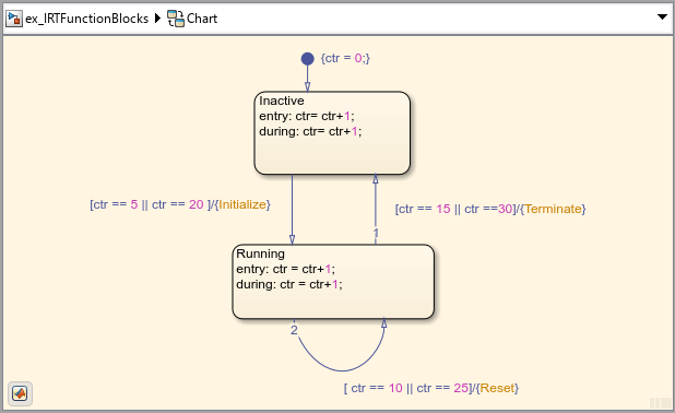
A Stateflow® chart is used to model an event schedule that generates the initialize, reset, and terminate function-call events. These function-call events control the execution of the ex_IRTFunctionBlocks model. For information about modeling the event scheduler and connecting the chart to the Model block, see Create Test Harness to Generate Function Calls.
Use Data Store to Model Nonvolatile Memory
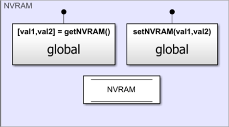
In this example, a data store is used to model a nonvolatile memory that stores Discrete-Time Integrator block state values at the root level of the ex_IRTFunctionBlocks model. For more information, see Data Store Basics.
The data store is created using a Data Store Memory block. A Data Store Read block inside the getNVRAM function and a Data Store Write block inside the setNVRAM function read and write the states of the Discrete-Time Integrator blocks respectively from the data store. For more information about creating data store, see Model Global Data by Creating Data Stores. This data store uses Simulink.Bus NVRAM that consists of Simulink.BusElement objects named s1 and s2. s1 corresponds to the Discrete Integrator1 block, and s2 corresponds to the Discrete Integrator2 block. For more information, see Data Store Memory, Data Store Read and Data Store Write.
Initial value of
s1is set to 5. The initial value ofs2is set to -5.

The function
getNVRAMuses the Data Store Read block to read the data from the Data Store Memory block. The State Writer block inside the Initialize Function and Reset Function blocks obtain the data from the data store and write to the Discrete-Time Integrator block states.

The State Reader block inside the Terminate Function block reads the Discrete-Time Integrator block state values. The function
setNVRAMuses the Data Store Writer block to write the data to the Data Store Memory block.

Results
The model executes based on the function-call events. The Discrete-Time Integrator block uses forward Euler accumulation integration method. For more information about the integration method, see Discrete-Time Integrator.
You can use the Scope block to view the output of both the Discrete-Time Integrator blocks at different time steps. The first row (channel1) and second row (channel2) of the Scope block represent the output of the Discrete Integrator1 and Discrete Integrator2 blocks respectively.
From the Scope block output, you can observe the following:
At time step 5, the Initialize Function block initializes the state of the
Discrete Integrator1block to 5 and theDiscrete Integrator2block to -5.At time step 10, the Reset Function block resets the state of the
Discrete Integrator1block to 5 while theDiscrete Integrator2block to -5.At time step 15, the Terminate Function block terminates the integration process for both the Discrete-Time Integrator blocks. The state value of both the blocks computed at time step 14 (15 for the
Discrete Integrator1block and -15 for theDiscrete Integrator2block) are written to the Data Store Memory block. The output computed at time step 14 represents the output from time step 15 through time step 19.At time step 20, the Initialize Function block is retriggered, and the states of both the Discrete-Time Integrator blocks are initialized to the state values stored in step 3.
At time step 25, the Reset Function block resets the states of both the Discrete-Time Integrator blocks to the state values stored in step 3.
At time step 30, the Terminate Function block terminates the integration processes of both the Discrete-Time Integrator blocks, and the states computed at time step 29 are written to the Data Store Memory block.

See Also
Initialize Function | Reset Function | Terminate Function | Event Listener