Use Connectors Tool to Visualize Relation Between Blocks
This example shows how to use the Connectors tool to visualize relation between Simulink® functions and their function caller blocks, reader and writer blocks or blocks which execute based on events. This visualization further helps to debug a model.
Use Function Connectors to identify Function Caller blocks and their corresponding Simulink Function blocks.
Use State Connectors to identify State Reader, State Writer and their corresponding state owner blocks. State owner blocks are blocks whose state values are read and written by the State Reader blocks and State Writer blocks, respectively.
Use Parameter Connectors to identify Parameter Writer blocks and their corresponding model workspace variables, base workspace variables, or parameter owner blocks. Parameter owner blocks are blocks whose parameter values are written by the Parameter Writer blocks.
Use Data Store Connectors to identify Data Store Read, Data Store Write and their corresponding Data Store Memory blocks.
open_system('ex_Connector')To visualize the connectors:
In the Simulink® Editor, on the Debug tab, select Information Overlays and click Connectors.
To view the connecting lines, in the Connectors pane that appears, select Function Connectors, State Connectors, Parameter Connectors, and Data Store Connectors.
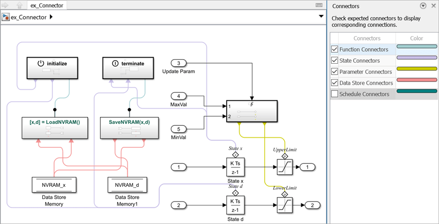
The connecting lines between different blocks represent the signal flow in the model. The arrow heads of the connecting lines indicate the direction of the signal flow.
See Also
Initialize Function | Terminate Function | Discrete-Time Integrator | Saturation