具有闭环控制的发动机定时模型
此示例说明如何为Model Engine Timing Using Triggered Subsystems中所述的开环发动机模型开发和实现闭环控制算法。在此示例中,模型 sldemo_enginewc 包含控制器,该控制器使用快速节气门作动器来调节发动机转速,以使负载转矩的变化产生的影响最小。该控制器是使用离散 PI 控制器实现的。
闭环模型

控制器方程
此示例使用比例积分 (PI) 控制器,如以下方程所示。


当设定值改变时,积分项会调节稳态节气门,比例项补偿由积分器引入的相位滞后。方程中的积分项通过离散时间逼近实现。控制器的执行与发动机的曲轴旋转同步,这也是工业中的典型情况。Controller 模型中的 sldemo_enginewc 子系统使用 Discrete PID controller 模块,该模块在离散时间内实现 PI 控制器,适合微处理器实现。每次触发子系统时,控制器都会执行。

仿真模型并可视化结果
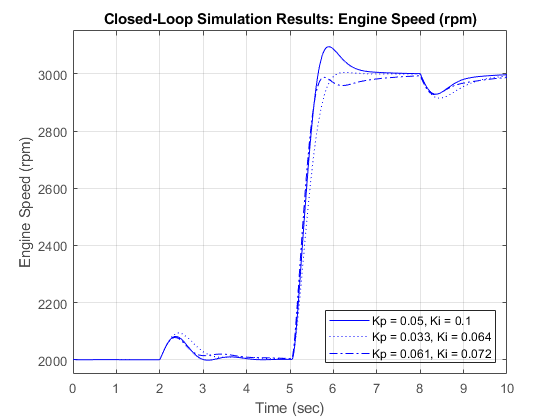
模型将输出数据记录到基础工作区中名为 sldemo_enginewc_output 的数据集中。您也可以使用 Simulink® 数据检查器可视化记录的信号。有关详细信息,请参阅仿真数据检查器。在 t = 5 秒处,转速设定值从 2000 rpm 升至 3000 rpm。转矩扰动与在开环模型 sldemo_engine 中使用的转矩扰动相同。控制器参数经过调节以实现具有零稳态误差的快速瞬态响应。稳态响应使用三组不同的 Ki 和 Kp 值来显示,这有助于了解比例 (Kp) 和积分 (Ki) 增益对发动机模型稳态响应的相对影响。您可以在 MATLAB® 命令行中调节 PI 控制器。

另请参阅
Triggered Subsystem | Subsystem Reference | Discrete PID Controller | Integrator | Second-Order Integrator
主题
- Model Engine Timing Using Triggered Subsystems
- Powertrain Blockset
- Convert Subsystem to a Referenced Subsystem
- Create and Use Referenced Subsystems in Models
- 为模型启用信号记录
参考
[1] Crossley, P. R., and J. A. Cook. “A Nonlinear Engine Model for Drivetrain System Development.” International Conference on Control 1991. Control ’91 1991, pp. 921–25 vol.2. IEEE Xplore, DOI.org (Crossref), https://ieeexplore.ieee.org/abstract/document/98573.
[2] The Simulink Model. Developed by Ken Butts, Ford Motor Company. Modified by Paul Barnard, Ted Liefeld and Stan Quinn, MathWorks®, 1994–7."
[3] Moskwa, John J., and J. Karl Hedrick. “Automotive Engine Modeling for Real Time Control Application.” 1987 American Control Conference, 1987, pp. 341–46. IEEE Xplore, DOIː 10.23919/ACC.1987.4789343.
[4] Powell, B. K., and J. A. Cook. “Nonlinear Low Frequency Phenomenological Engine Modeling and Analysis.” 1987 American control conference, 1987, pp. 332–40. IEEE Xplore, DOIː 10.23919/ACC.1987.4789342.
[5] Weeks, Robert W., and John J. Moskwa. “Automotive Engine Modeling for Real-Time Control Using MATLAB/SIMULINK.” SAE transactions, vol. 104, 1995, pp. 295–309. JSTOR, https://www.jstor.org/stable/44473229.