Model and Control Robot Dynamics to Automate Virtual Assembly Line
This example extends the Smart4i virtual commissioning applications to accommodate robot dynamics in the system framework to automate assembly line operation. This example models the digit twin of the Smart4i setup and controls the dynamics of robots in the assembly line, which helps develop a more realistic simulation environment. The virtual assembly line consists of four components: two robotic workcells, connected by a shuttle track and a conveyor belt. The first robot, Robot 1, is a Comau Racer V3 and places cups onto the shuttle. The second robot, Robot 2, is a Mitsubishi RV-4F and places balls in the cups. The shuttle track system consists of four shuttles which continuously move to Robot 1, then to Robot 2, followed by a slider. A slider then delivers those cups containing balls to a container. For a detailed system overview, see Automate Virtual Assembly Line with Two Robotic Workcells (Robotics System Toolbox).
Model Overview
Open the model to view the block diagram:
open_system("smart4iRobotDynamics.slx")
The model consists of three main parts:
Scene Creation & Configuration
System Control Logic
Simulink 3D Actor Visualization
The Scene Creation & Configuration section sets up the baseline Unreal Engine® environment comprising of static machine frame, robot workcells, shuttle track, and conveyor belt. The System Control Logic section models and controls the assembly line operations in Simulink® using Robotics System Toolbox™ to model and control the dynamics of robots, and use Stateflow® logic to model the shuttle control and cup movement. The Simulink 3D Actor Visualization section moves the objects created using Simulink 3D Animation™ by translating the motion commands to the actors in the scene. It defines the motion of the two robots, four shuttles, and the position of the ball. This example covers the System Control Logic section, but there are minor changes to the Stateflow logic and Simulink 3D Actor Visualization in this example to accommodate the introduction of robot dynamics. For more details about the Scene Creation & Configuration, and Simulink 3D Actor Visualization, see Automate Virtual Assembly Line with Two Robotic Workcells (Robotics System Toolbox).
Robot Motion Control
The subsystems Robot1 Motion Control and Robot2 Motion Control, model and control the Comau and Mitsubishi robots, respectively. These two subsystems form the core of the system model.
Robot1 Motion Control Subsystem
The Robot1 Motion Control subsystem has two inputs, r1Go and r1Sh, from the Stateflow logic to determine the current task, generating the waypoints and current state. r1Go denotes whether Robot 1 is ready to operate and r1Sh denotes the shuttle number to place a cup into. The subsystem outputs the current joint configuration of Robot 1, r1Pos, and the current operating state of Robot 1, r1State.
Open the Robot1 Motion Control subsystem.

The subsystem consists of two subsystems:
Task Scheduling & Waypoint Generation
Robot1 Dynamics and Control
Task Scheduling & Waypoint Generation
This component defines waypoints that the robot should traverse to achieve the desired operation. If Robot1 is ready to operate (r1Go==1), then the model executes the Robot1 Reference Waypoints subsystem. Otherwise the robot remains in its home configuration, defined in the Home Configuration1 subsystem.

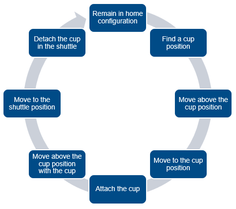
These are the tasks that Robot1 executes, in this order:
Remain in home configuration
Find a cup position
Move robot end effector to a position directly above the cup
Move robot end effector to the cup position
Grip the cup with the end effector
Lift the cup
Move to the position of the available shuttle
Release the cup into the shuttle
Return to the home configuration to repeat these tasks again

The task schedule logic is implemented using a MATLAB Function block, commandLogic. The model uses MATLAB Function blocks to implement MATLAB functions such as findCup, attachCup, detachCupPhys1, and detachCupPhys2 in Simulink. findCup function determines the XY-coordinates of the cup position. The attachCup function attaches the cup to robot manipulator. The detachCupPhys1 and detachCupPhys2 functions detach the cup into a shuttle. The model uses triggered subsystems to achieve grip and release cups, shown in this image.

Robot1 Dynamics and Control
To find the joint configurations from desired end-effector positions, the model uses the Inverse Kinematics (Robotics System Toolbox) block to convert XYZ-coordinates waypoints from the Task Scheduling & Waypoint Generation subsystem, based on the imposed constraints in the robot rigid body tree model. The Trapezoidal Velocity Profile Trajectory (Robotics System Toolbox) block takes these configurations and generates a smooth trajectory between each joint configuration.

The Torque Controller subsystem computes the applied torque using Robotics Manipulator blocks such as Joint Space Mass Matrix (Robotics System Toolbox), Velocity Product Torque (Robotics System Toolbox), and Gravity Torque (Robotics System Toolbox), in combination with PD control logic. For more details, see Build Computed Torque Controller in the Perform Safe Trajectory Tracking Control Using Robotics Manipulator Blocks (Robotics System Toolbox) example. Note that all of the robotics manipulator blocks in this subsystem use the rigid body tree, Robot1.
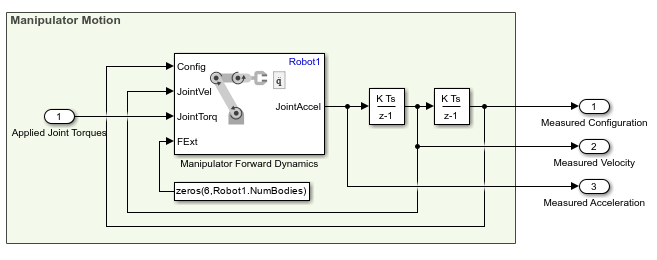
Given torque inputs, Manipulator Dynamics subsystem represents the manipulator joint positions. This is achieved using the Forward Dynamics (Robotics System Toolbox) block to convert joint torques to joint acceleration given the current state, and then integrating twice to get the complete joint configuration.

Robot2 Motion Control
The Robot2 Motion Control subsystem has three inputs, r2Go, r2Sh, and ballInst from the Stateflow logic to the subsystem. r2Go indicates whether Robot 2 is ready to operate and r2Sh indicates the number of the shuttle that is containing a cup. The subsystem outputs, r2Pos and r2State. r2Pos indicates the current joint configuration of Robot 2, and r2State denotes whether Robot 2 is currently operating. As a part of Stateflow logic, note that a ball instance in Robot 2 workcell gets created when shuttle exits Park 2 and moves towards workcell of Robot 2. Correspondingly, ballInst denotes the instance of the ball created and the model uses this value for the findBall and attachBall functions. The series of tasks that Robot 2 executes are similar to Robot 1, except that Robot 2 picks ball from its workcell and places it into the cup in the shuttle. Thus, the design architecture of Robot2 Motion Control subsystem follows Robot1 Motion Control subsystem. Open the Robot2 Motion Control subsystem for more details.

Joint Angle Limitation
Introducing robot dynamics also helps in incorporating joint limitations, which constrains the joint positions of robot manipulators to ensure that the robot moves realistically. The model enforces the joint limits by setting the PositionLimits property of associated rigidBodyTree objects of each robot. The Inverse Kinematics block enforces these constraints while computing joint configurations for the desired manipulator position. To enforce the joint limits, ensure that you select the Enforce joint limits solver parameter in the Inverse Kinematics block.
Joint | Robot 1 Joint Limits (degrees) | Robot 2 Joint Limits (degrees) |
1 |
|
|
2 |
|
|
3 |
|
|
4 |
|
|
5 |
|
|
6 |
|
|
System Simulation
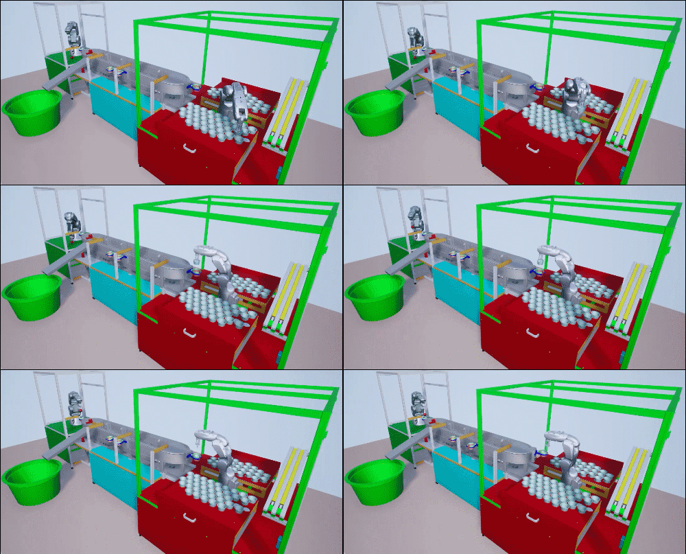
In the Simulink model, click Run to start the simulation. The simulation might take a minute to start in Simulation 3D Viewer as Unreal Engine takes time to initialize the actors in the scene. Visualize the complete operation in the Simulation 3D Viewer.

See Also
Joint Space Mass Matrix (Robotics System Toolbox) | Velocity Product Torque (Robotics System Toolbox) | Gravity Torque (Robotics System Toolbox)
Topics
- Automate Virtual Assembly Line with Two Robotic Workcells (Robotics System Toolbox)
- Generate Automated ros_control Plugin for 3-D Shape Tracing Manipulator (Robotics System Toolbox)
- Perform Safe Trajectory Tracking Control Using Robotics Manipulator Blocks (Robotics System Toolbox)