Estimate Battery Current of PMSM in Open-Loop Control Using Arduino Hardware
This example shows how to use Simulink® Support Package for Arduino® Hardware to estimate the battery current of a permanent magnet synchronous machine (PMSM) in open-loop control using Motor Control Blockset™. This example also shows how to actuate a PMSM motor and calculate phase currents that are indirectly used to estimate the current of the battery.
Open-loop control is a motor control technique that you can use to run any AC motor. This technique does not include any feedback from the motor. This technique varies the stator voltage and frequency to control the rotor speed without using any feedback from the motor. For more information on open-loop motor control, see Open-Loop and Closed-Loop Control (Motor Control Blockset).
Prerequisites
Download and install Embedded Coder®.
For more information on how to use Simulink Support Package for Arduino Hardware to run a Simulink model on your Arduino board, see Get Started with Arduino Hardware.
For more information on how to use the Hardware Interrupt block to generate an ISR to react to the PWM events on the Arduino hardware, see Generate Interrupts Using Arduino SAMD PWM Block.
For more information on how to use the SAMD event system with Arduino Advanced PWM, Analog Input, and Hardware Interrupt blocks, see Get Started with Arduino SAMD Event System Using PWM and ADC Peripherals.
Supported Arduino Boards
Arduino MKR 1000
Arduino MKR Zero
Arduino MKR WiFi 1010
Arduino Nano 33 IoT
Required Hardware
This example uses the Arduino Nano 33 IoT board. You can use any of the boards listed in the Supported Arduino Boards section.
PMSM motor
Ti-Motor Bridge Driver BOOSTXL-DRV8305EVM
Connecting wires
24-V DC supply
Hardware Setup
Connect a 24-V DC supply source to the supply header of the DRV8305EVM driver.
Connect the PMSM motor to the motor header of the DRV8305EVM driver.
Connect the DRV8305EVM driver and the Arduino Nano 33 IoT board as shown in the following image.
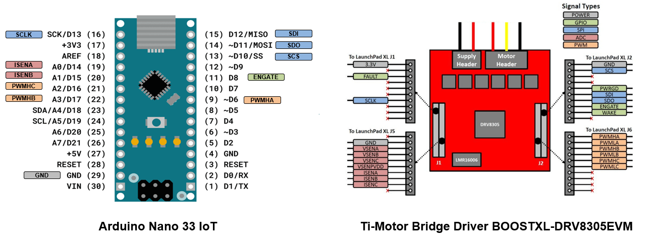
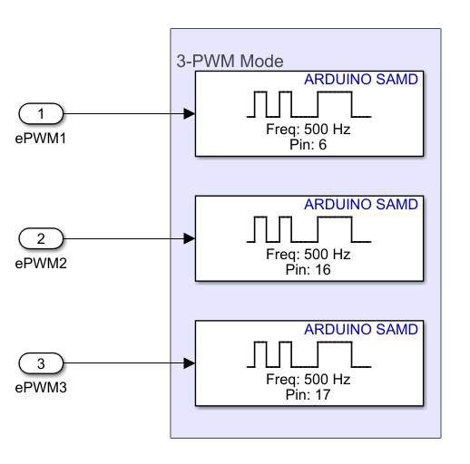
Note: In this example, the connections between the Arduino Nano 33 IoT and the DRV8305EVM driver are for the 3PWM mode. The 3PWM mode channels PWMHA, PWMHB, and PWMHC are connected to Arduino GPIO pins 6, 16, and 17 respectively. The phase current inputs ISENA and ISENB are connected to Arduino GPIO pins 14 and 15, respectively. Connect GPIO pin 8 of the Arduino board to the ENGATE pin of the DRV8305EVM driver. Connect GPIO pin 10 of the Arduino board to the SCS (chip select) pin of the DRV8305EVM driver.
Configure Simulink Model and Calibrate Parameters
Open the arduino_mcb_openloop_control Simulink model.
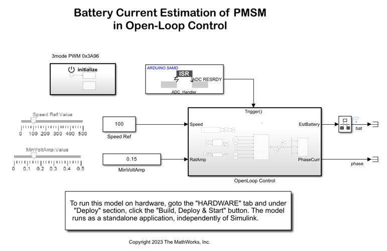
Initialize
Enable the gate driver and select the PWM mode of operation.
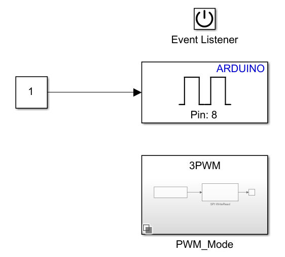
To enable the gate drivers of the DRV8305EVM driver, write a logical 1 to the GPIO pin 8 of the Arduino board using the Digital Output block.
Double-click the PWM_Mode subsystem. The 3PWM mode is selected by default. In the SPI WriteRead block, set the Chip select (CS) pin parameter to 10 to access the DRV8305EVM driver. To enable the 3PWM mode of operation for the gate driver, input the value 0x963A to the SPI WriteRead block.
To enable the 6PWM mode of operation for the gate driver, right-click the PWM_Mode subsystem and select Block Parameters (Subsystem). In the Variant Subsystem block mask, set Label mode active choice to 6PWM_Mode (6PWM).
ADC Interrupt
The Hardware Interrupt block is configured to generate an interrupt when the ADC peripheral on the Arduino hardware has completed the analog to digital conversion.
Configure these parameters in the Hardware Interrupt block.
Set Interrupt group to
Analog to digital converter (ADC).Set Interrupt name to
ADC_Handler.In the Events to server section, select
ADC RESRDY.
Open-Loop Control
Run the PMSM motor by using an open-loop motor control algorithm.
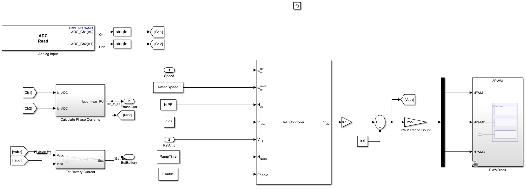
1. Read Motor Phase Currents Using Analog Input Block
Use the Analog Input block to read the input phase currents on the ADC channel 0 (ISENA) and ADC channel 1 (ISENB).
Configure these parameters in the Analog Input block.
Set Number of analog input pins to
2.Set Pin number 1 to
0.Set Pin number 2 to
1.Select Enable end of conversion interrupt.
2. Implement V/f Control for PMSM Motor Using VbyF Controller
The VbyF Controller (Motor Control Blockset) block implements V/f control of the PMSM motor where the speed of the motor is controlled with stator voltage and frequency. Specify the motor parameters in the arduino_mcb_openloop_control_data.m file. These parameters act as an input to the VbyF Controller (Motor Control Blockset) block. The block outputs PMSM motor phase voltages Vabc that drive the motor. The output voltages Vabc are multiplied by a gain factor of 0.5. The peak to peak value of the voltages is converted from [-0.5, 0.5] to [0, 255].
3. Generate Waveforms on PWM Channels
You can generate three phase waveforms ePWM1, ePWM2, and ePWM3 for the PMSM motor voltages Vabc and control its duty cycle.
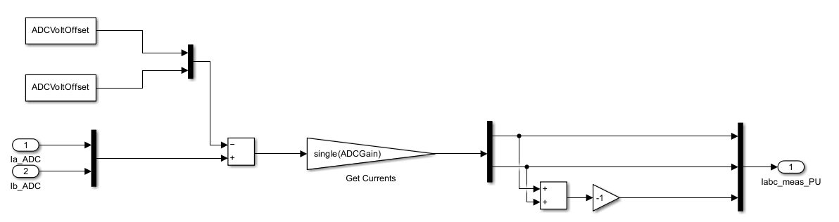
4. Calculate Phase Currents Using Kirchhoff's Current Law (KCL)
The inputs to this subsystem are the phase currents read on ADC channel 0 (ISENA) and channel 1 (ISENB). Ia_ADC and Ib_ADC are the voltage equivalent of the currents when the PWM input signal is on, that is, the duty cycle of the signal lies between 0 to 100%. ADCVoltOffset are the voltage equivalent of the currents when the PWM signal is off, that is, the duty cycle of the signal is 0. Using the KCL, the third phase current is calculated.
The block calculates the ADC gain based on the shunt resistor value and the resolution of the ADC. See the ADCGain parameter in the arduino_mcb_openloop_control_data.m file.
5. Estimate Battery Current
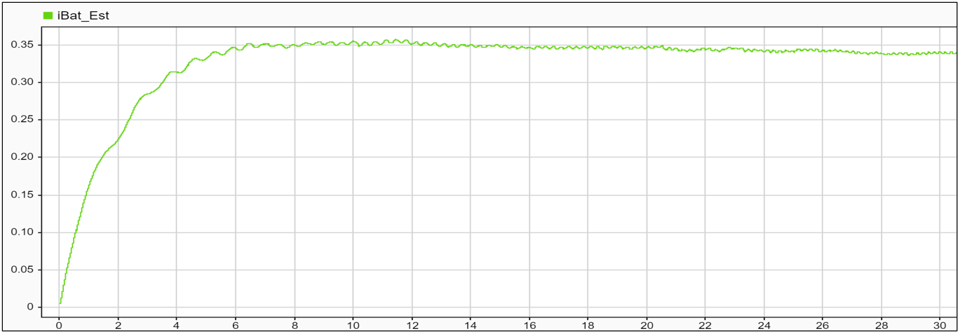
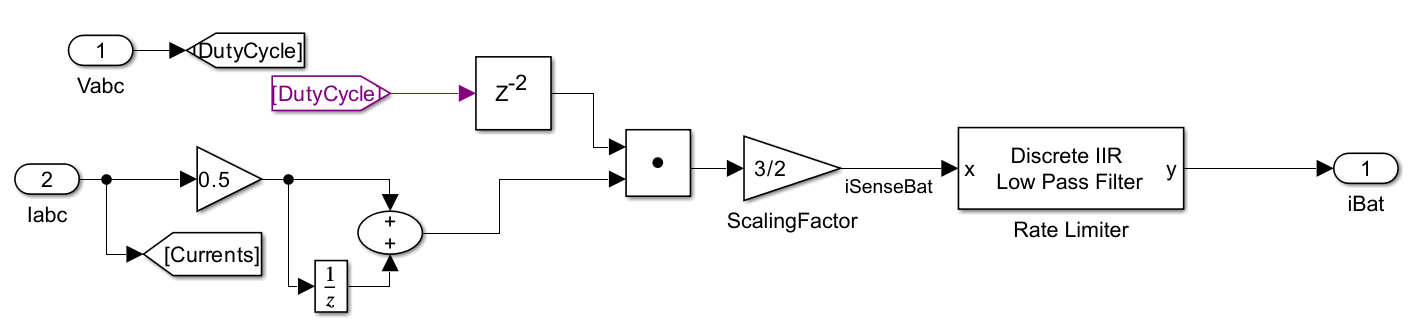
The inputs to this subsystem are the three phase currents Iabc and voltages Vabc. To make the Vabc and Iabc synchronous in time, a delay (z^-2) is added to the Vabc signal. The dot product of the Vabc and the averaged Iabc signals gives the estimated battery current. This signal is passed through a lowpass filter to eliminate the high frequency oscillations in the signal.
Run Simulink Model in External Mode
To run the Simulink model in external mode, on the Hardware tab of the model, click Monitor & Tune. Use the sliders on the Simulink model to control the speed and the minimum voltage-ampere input to the PMSM motor. Connect a scope and observe these parameters from the Simulink model.
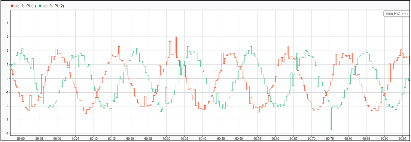
Phase Currents Ia_ADC Ib_ADC
Estimated Battery Current iBat_Est