Deploy Controller for SEPIC Converter for PIL Testing
This example shows how to set up processor in the loop (PIL) testing and profiling of an active disturbance rejection controller on a Texas Instruments® TMDSDCDCLEDKIT with a Piccolo F28069 control card. In a PIL simulation, the control algorithm executes in the target hardware, but the plant model runs on the host machine. The plant model simulates the input and output signals for the controller and communicates with the controller by using the serial communication interface. This functionality allows you to use PIL simulation to determine the execution time on the target hardware and test whether the model and the generated code are numerically equivalent.
Required MathWorks Products
Simscape™ Electrical™
C2000™ Microcontroller Blockset
Simulink® Control Design™
Embedded Coder®
Supported Hardware
Texas Instruments TMDSDCDCLEDKIT with a Piccolo F28069 control card
Prepare PIL Model
This example uses the active disturbance rejection control for a (ADRC) for a single-ended primary-inductor converter (SEPIC) converter modeled in Simulink using Simscape Electrical components. For more information, see Design Active Disturbance Rejection Control for SEPIC Converter. This example also provides a model scdSEPICConverterADRC_PIL, preconfigured with the steps described in this example. Note that you may need to reconfigure the model on the hardware you have.
Open the model.
mdl = "scdSEPICConverterADRC";
open_system(mdl);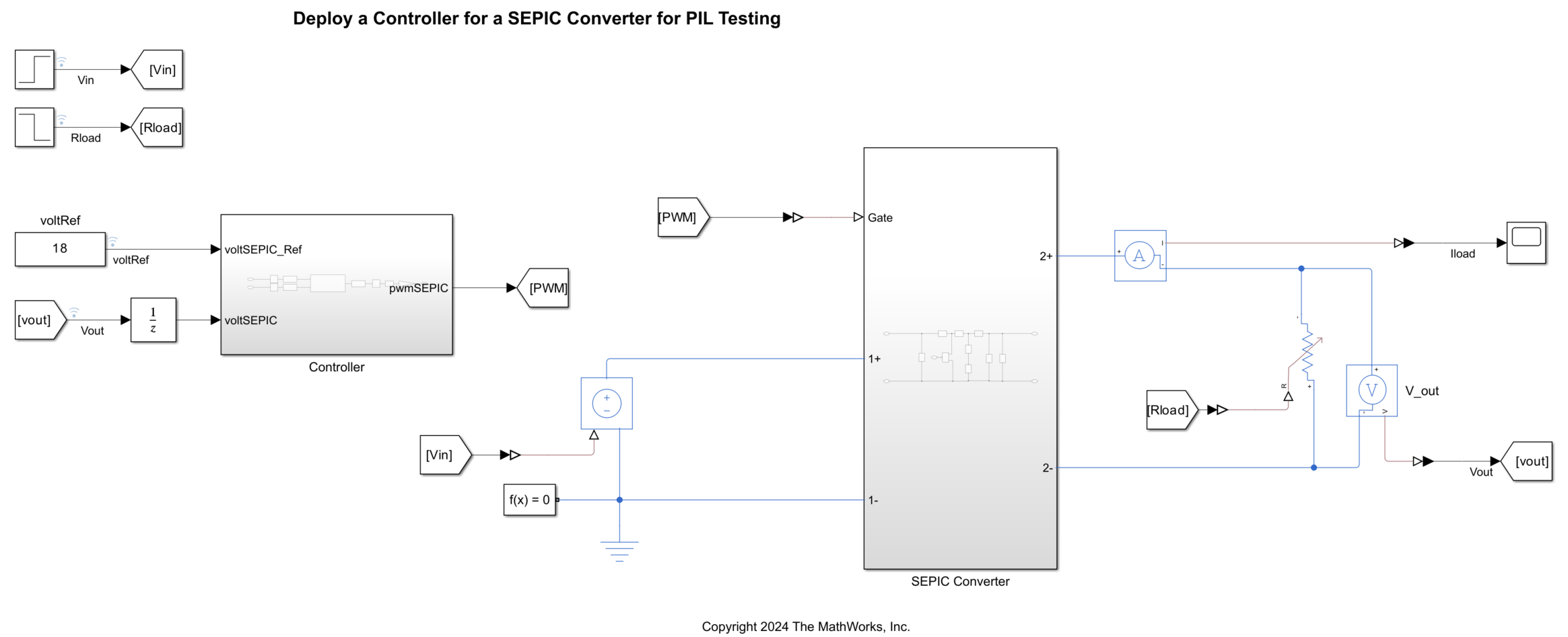
To simulate the ADRC and PI controller for closed-loop voltage control, under the Controller subsystem, this model contains the variant subsystem Control algorithm. You configure these blocks for processor-in-the-loop simulation.
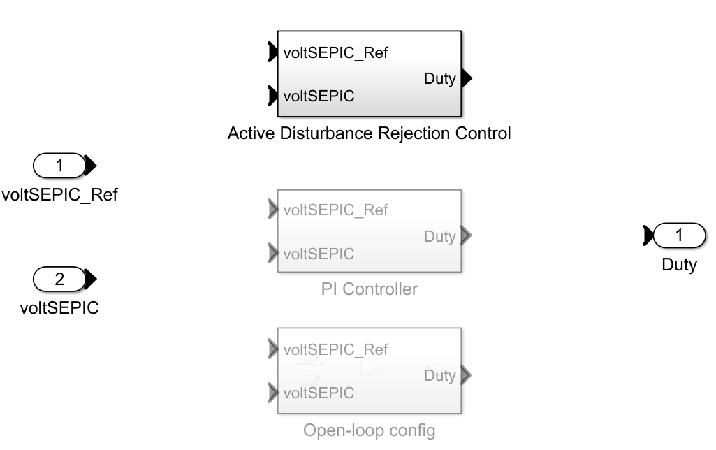
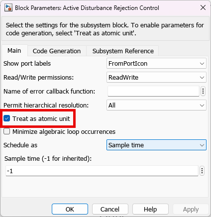
Right click on the Active Disturbance Rejection Control subsystem, under Block parameters, check Treat as an atomic unit.
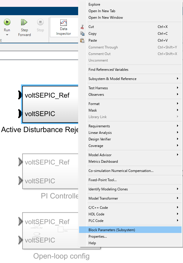
Then convert the subsystem into a model reference, under Subsystem & Model Reference > Convert to > Referenced Model.
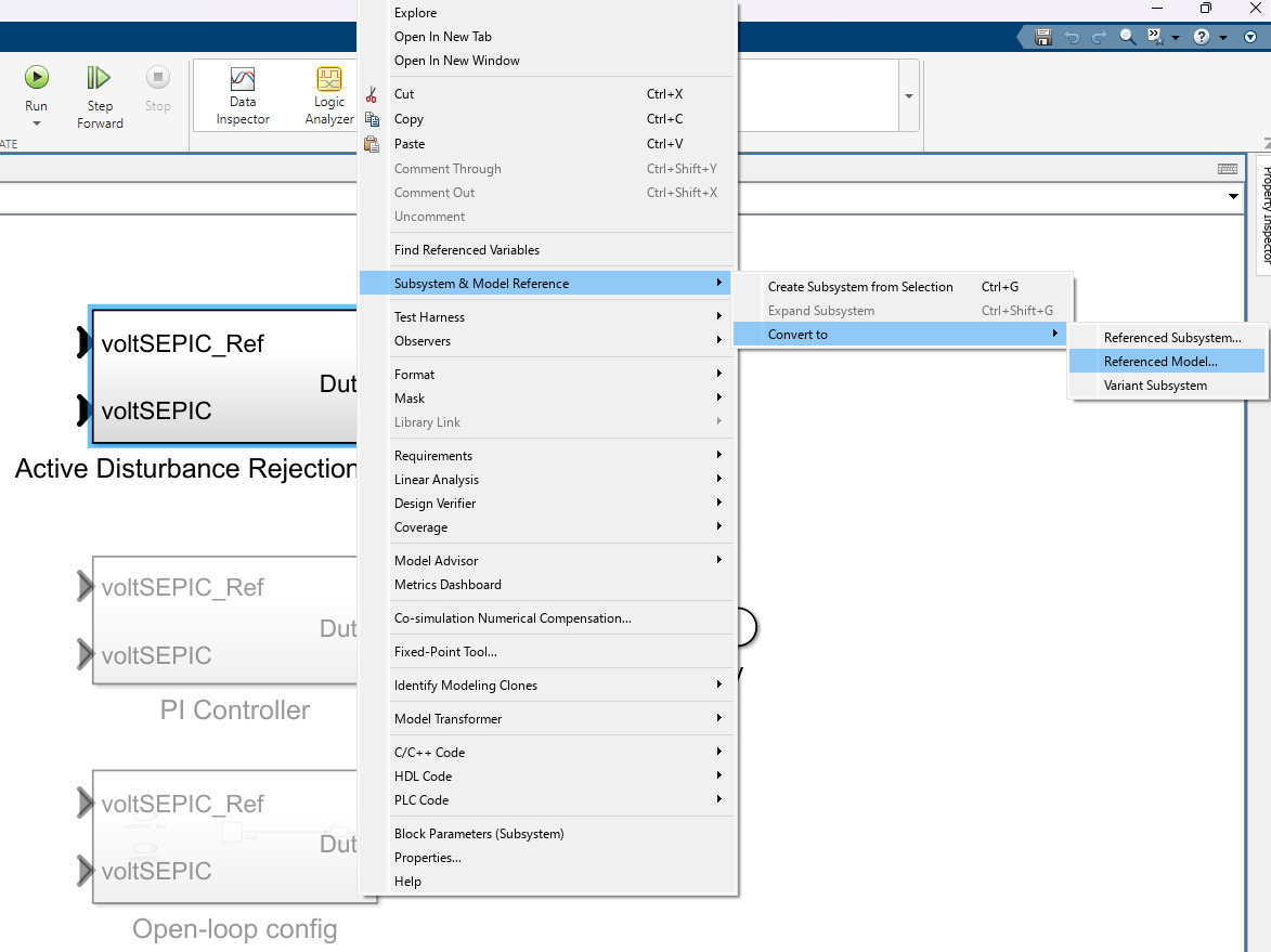
This will open the Model Reference Conversion Advisor to convert subsystems into model references. If for any case, the conversion runs into any issues, the advisor will help you review and fix the issues. Click on Convert.

This should run the checks and convert subsystem into a model reference.

Repeat the step above to set up the PI controller as a model reference after labeling it as the active controller variant.
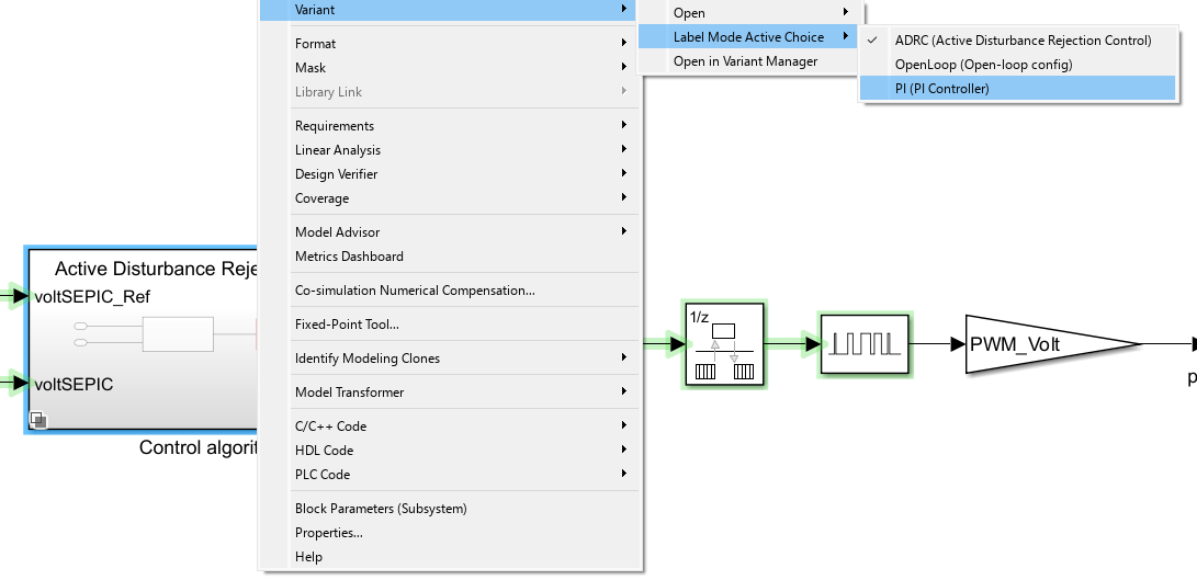
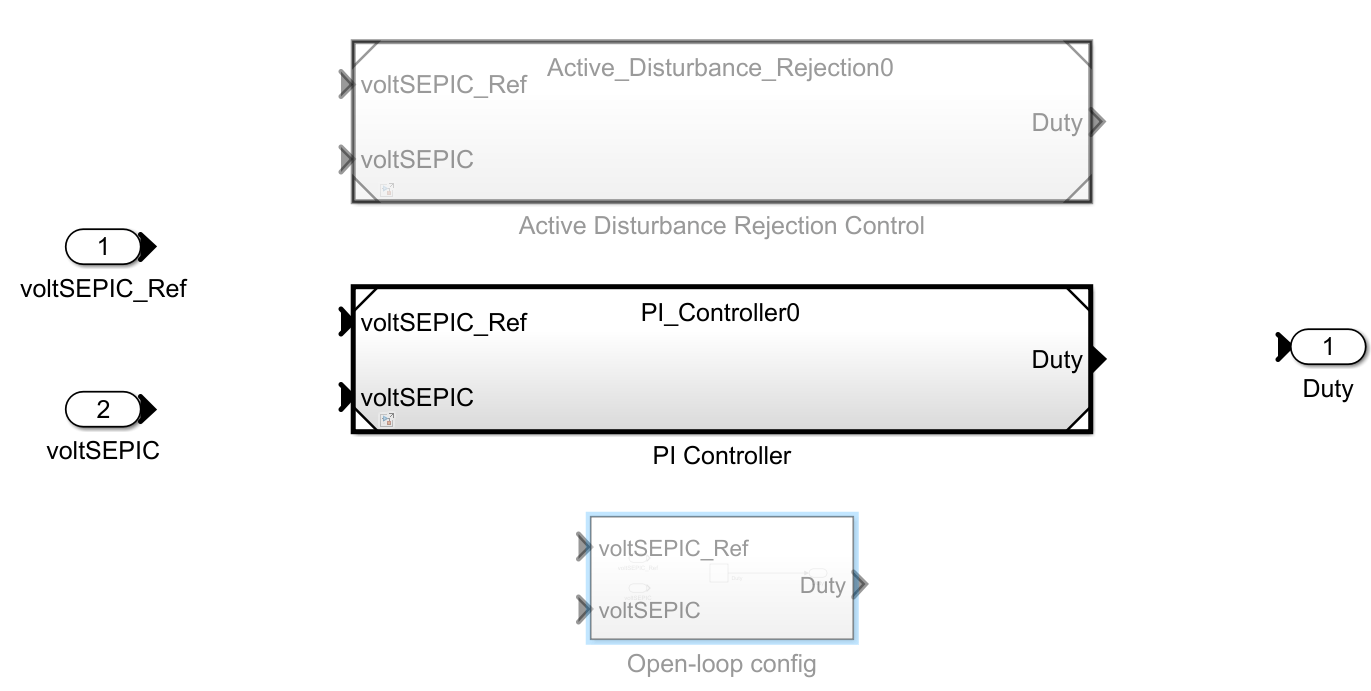
Right click the PI controller model reference and open it as a top-level model. In the Modeling tab, click Model Settings. Then, in the Configuration Parameters dialog box, under Hardware Implementation, set the Hardware board field to TI Piccolo F2806x LaunchPad.
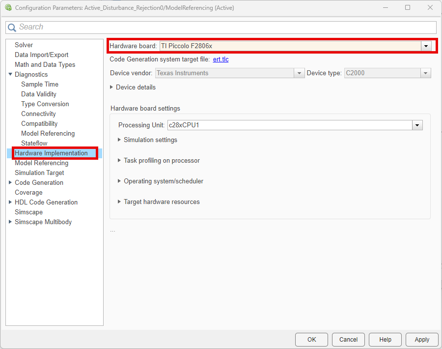
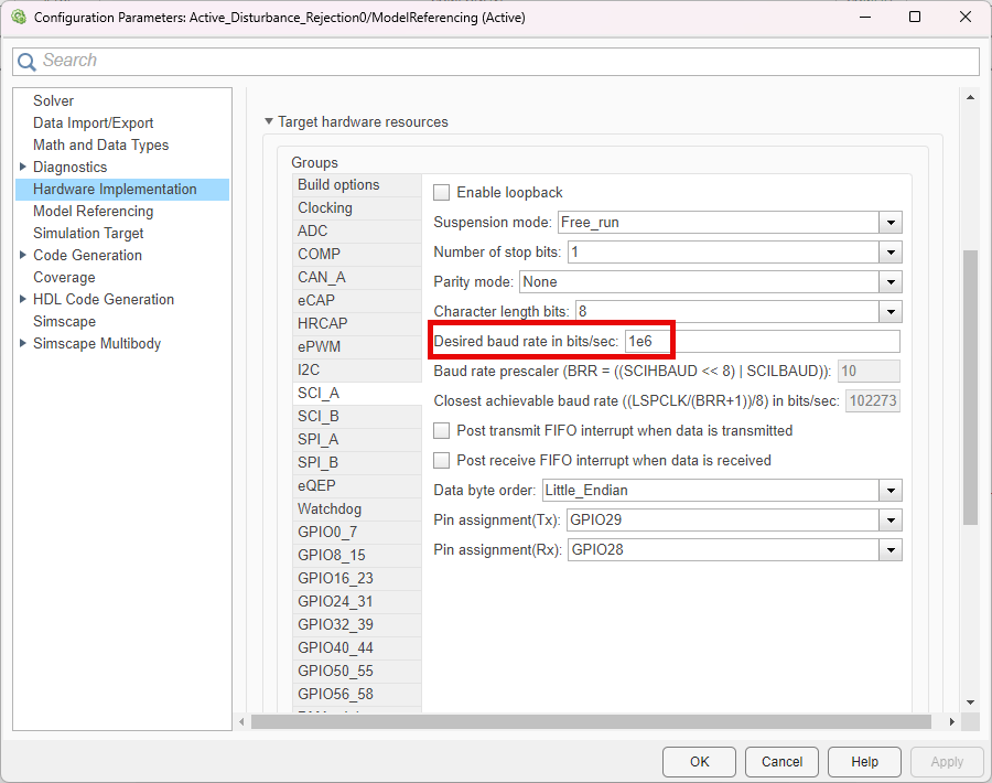
In the Configuration Parameters dialog box, select these configuration settings under Hardware Implementation > Hardware board settings > Target hardware resources > SCI_A:
Desired baud rate in bits/sec - 1e6
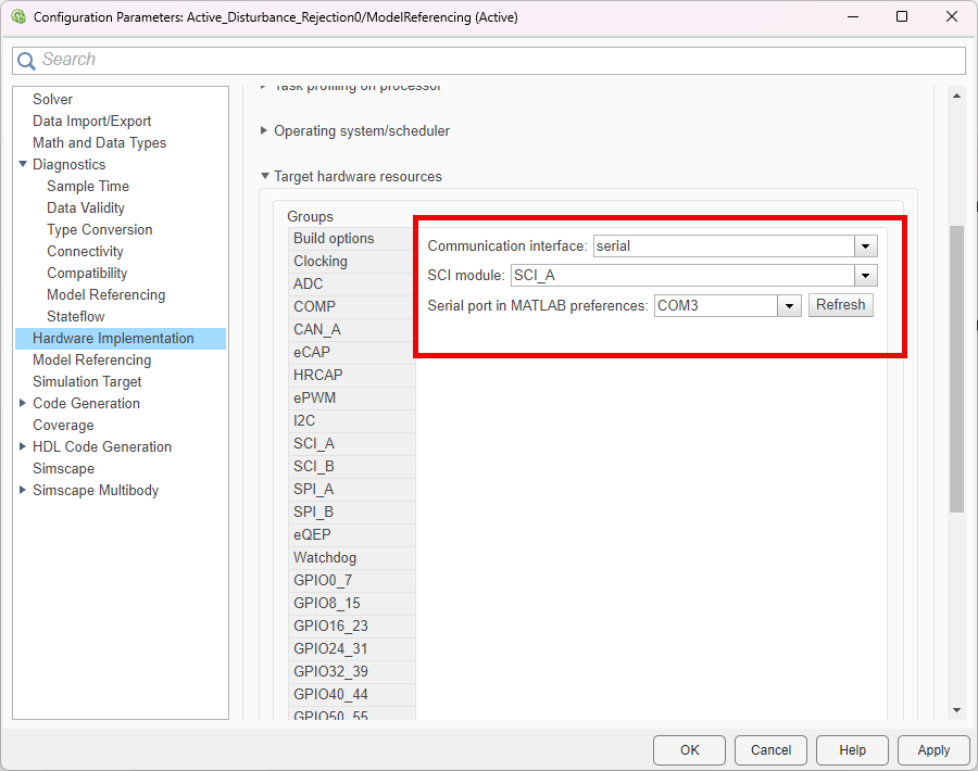
Additionally, select the following configuration settings under Hardware Implementation > Hardware board settings > Target hardware resources > PIL:
Communication Interface - Select
serial.SCI module - Select
SCI_A.Serial port in MATLAB preferences - The model automatically detects the communication port to which you have connected the hardware. This parameter remains unchanged for the rest of the currently active MATLAB® session. Click the Refresh button to detect the communication port again.
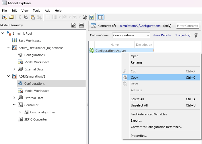
Copy the model configuration settings to the ADRC model reference. You can do this from the Model Explorer in the Modeling tab of Simulink. Copy the active configuration from the PI Controller model and paste it into the configurations of the Active_Disturbance_Rejection0. Right click on the copied configuration and activate it.

Set up the model references to run in PIL mode. You can do this by right clicking on the model references and under Block Parameters, select Processor-in-the-loop (PIL) in the Simulation mode drop down.

Enable PIL profiling in the Configuration Parameters dialog box, by checking the Measure task execution time under Code Generation > Verification.

You have now set up both the ADRC and PI controllers to run in PIL mode. Select the ADRC controller as the active variant. Click the Run button on the Simulink toolstrip. This will build the Active Disturbance Rejection Control (PIL) subsystem and deploy it to the C2000 target.
After the system deploys the subsystem, the Active Disturbance Rejection Control (PIL) subsystem executes on the target hardware processor, while the plant model runs on the host machine.
Analyze PIL Profiling Results
When PIL simulation ends, the system generates a profiling report.
Note that PIL simulation takes more time than the host-machine-based simulation. This is because of the serial communication (related to inputs and outputs of the Active Disturbance Rejection Control (PIL) subsystem) between the host machine and subsystem that runs on the target hardware.
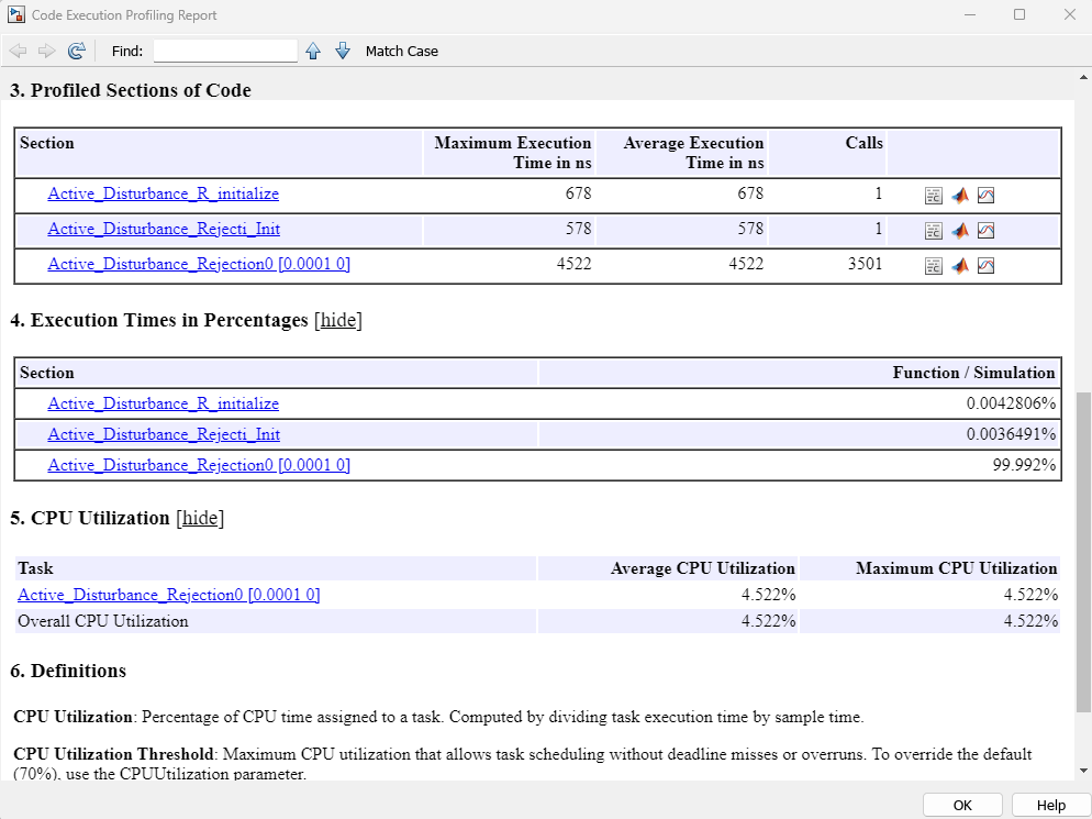
This profiling report shows metrics such as maximum and average execution times of the Active Disturbance Rejection Control (PIL) subsystem, maximum and average CPU utilization of the target hardware.
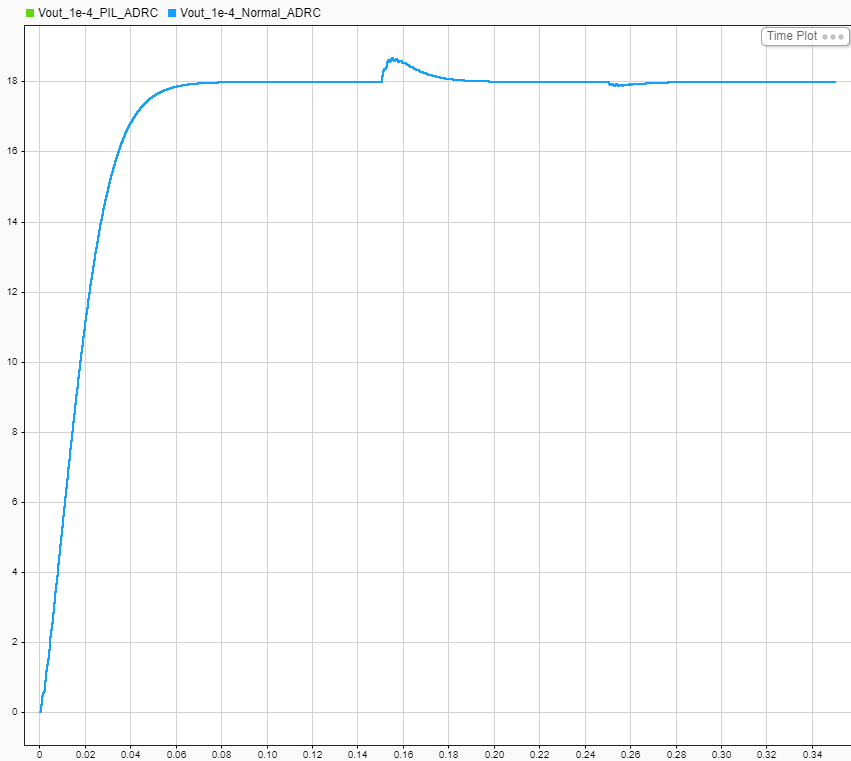
You can use the Data Inspector button on the Simulation tab to compare the signals logged during host-machine-based simulation and PIL simulation (executed on the target). This helps you verify the accuracy of host-machine-based simulation and PIL simulation.
This plot compares the voltage feedback signals from the Active Disturbance Rejection Control (PIL) and Active Disturbance Rejection Control subsystems.
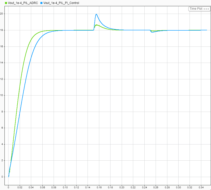
You can also compare the results of the PI Controller (PIL) with the Active Disturbance Rejection Control (PIL) subsystems.
See Also
Active Disturbance Rejection Control
Topics
- Design Active Disturbance Rejection Control for SEPIC Converter
- Design Active Disturbance Rejection Control for Water-Tank System
- Design Active Disturbance Rejection Control for Boost Converter
- Design Active Disturbance Rejection Control for BLDC Speed Control Using PWM
- Implement PMSM Speed Control Using Active Disturbance Rejection Control (Motor Control Blockset)