主要内容

Improve Test Completeness by Extending Requirements-Based Tests

R2026b

In model-based design, requirements define the expected behavior of a component or system. You derive functional tests from these requirements to verify that the implementation satisfies its intended behavior. As the design evolves, you execute these tests and review coverage results to assess verification completeness. For more information on functional tests, see Functional Testing for Verification (Simulink Test).

There are two common approaches to write functional tests. In the black-box approach, you write functional tests from requirements and use them to verify their implementation. These tests achieve the intended verification objectives but can leave portions of the implementation untested. Uncovered objectives may indicate missing test cases, incomplete requirements, dead logic, or implementation issues. For more information, see Test Model Against Requirements and Report Results (Requirements Toolbox).

The white-box approach uses requirements, existing tests, and implementation details together. Coverage analysis identifies model behavior that current tests do not consider, which helps you find missing requirements, incomplete tests, implementation issues, or dead logic. Although this approach relies on implementation details, it helps in identifying missing or conflicting requirements and is effective during later stages of testing.

Simulink® Design Verifier™ analyzes a model together with the existing functional tests in the Test Sequence harness and generates additional test cases. The generated tests:

  • Are derived from the input test cases

  • Add only the additional steps required to exercise uncovered objectives

  • Include information that identifies their relationship to the original user-authored tests

Workflow

To generate additional test cases with Simulink Design Verifier, use this workflow, which workflow combines coverage-driven analysis with engineering review to improve verification completeness.

  1. Create functional tests from requirements and run them against the model.

  2. Collect model coverage to identify uncovered objectives in the implementation.

  3. Use Simulink Design Verifier to analyze the model together with the existing test sequence. Simulink Design Verifier generates tests that extend the original behavior to cover the remaining objectives.

  4. Compare the additional behavior with the original requirements. Determine whether the generated scenarios represent meaningful functionality or indicate issues such as dead logic or incomplete requirements.

  5. After review, incorporate the test extensions into the functional test suite as additional requirements-based tests.

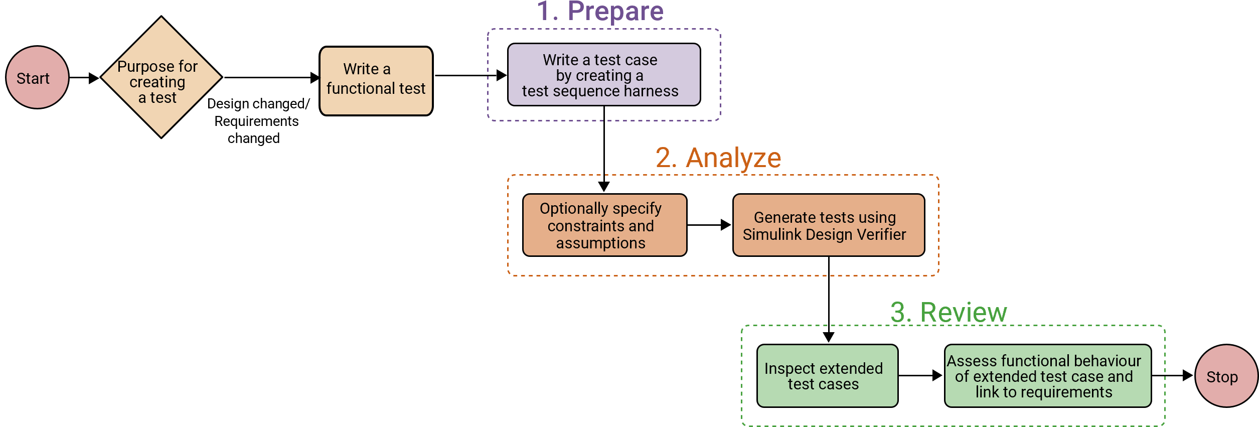
Flowchart showing the workflow for creating a functional test case for test generation.

Generate Additional Functional Tests by Extending Existing Requirements-Based Tests

This example shows how you can use Simulink® Design Verifier™ to create additional test scenarios from existing functional tests. Instead of generating tests from scratch, Simulink Design Verifier extends an existing user-authored test sequence and generates new tests that exercise previously uncovered model behavior while preserving the intent of the original test. You review the relationship between the generated tests and the original tests after the analysis and convert the reviewed test extensions into additional functional tests that improve model coverage. For more information on functional testing, see Perform Functional Testing and Analyze Test Coverage.

Requirements

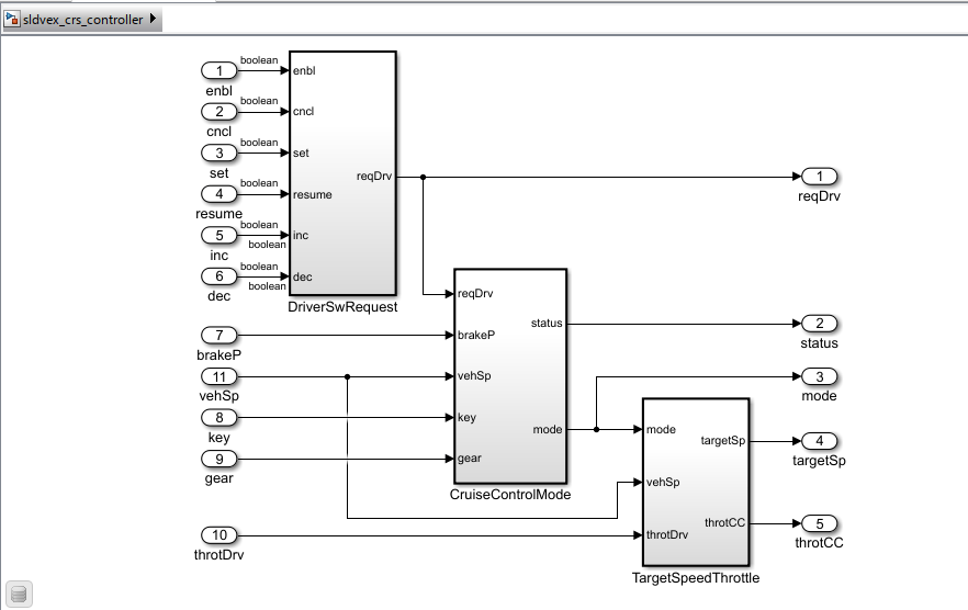
Verify the model sldvex_crs_controller using requirement-based tests.

Open the model:

open_system("sldvex_crs_controller");

The requirement #29 Activate conditions in the requirements set sldvex_crs_req_func_spec states that the cruise control system activates only when the driver performs the correct sequence of actions under valid conditions.

The requirement states that the cruise controller shall activate when the driver presses the set speed, or increment, button and the vehicle speed is at least 40 km/h. Write a test case to verify this requirement using this sequence of steps:

Step

Action in Test Sequence

Expected Behavior

1

Turn ignition on.

Vehicle enters the running state.

2

Increase speed above 40 km/h.

Activation condition for cruise control is satisfied.

3

Press the button to enable cruise control.

Cruise control is enabled.

4

Press the button to set or increment cruise control.

Cruise control activates.

This scenario represents an expected real-world interaction and forms the basis of a functional test in a time-based, scenario-driven format.

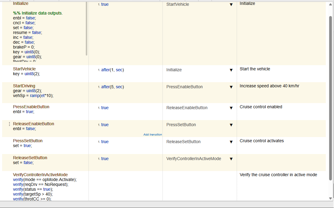
The model sldvex_crs_controller contains a test harness model TestControllerActivation_Harness that contains the tests using a Test Sequence block. A Test Sequence block lets you express intended system behavior as a readable functional scenario.

Open the test harness:

sltest.harness.open("sldvex_crs_controller", "TestControllerActivation_Harness");
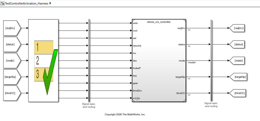
Test Design Using a Test Sequence Block

Double-click the Test Sequence block in TestControllerActivation_Harness model to view the actions of driver interaction as a sequence of steps. For more information, see Test Sequence (Simulink Test) block.

Simulate the Top Model and Generate Tests

1. In the Apps tab of Simulink® Toolstrip, open Design Verifier.

2. In the Analyze section of the toolstrip, click the Remember Selection icon to unpin the current selection.

3. Select the Model block sldvex_crs_controller. In Design Verifier tab, click Generate Tests > Simulate Top Model And Generate Tests.

Simulink Design Verifier generates test cases for the Model block component. The Results summary window shows that out of 76 objectives, 35 objectives are satisfied and 41 objectives were satisfied by existing test or coverage data. To access the detailed analysis report, click HTML.

Inspect the Results

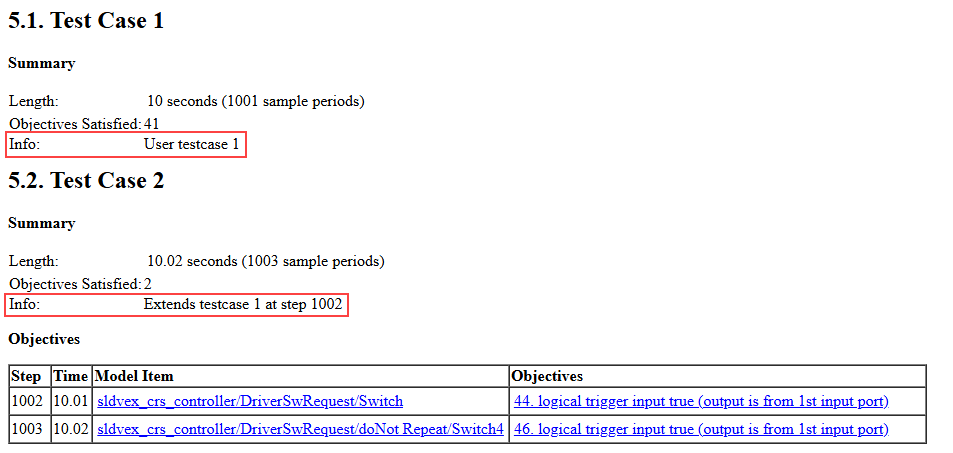
In the Simulink Design Verifier report, click Test Cases. The generated test cases reuse the original activation sequence. The analysis extends the Test Case 1 to generate Test Case 2.

Test Case 2 preserves steps 1-1001 from Test Case 1 and modifies steps 1002 onward to satisfy the new objectives.

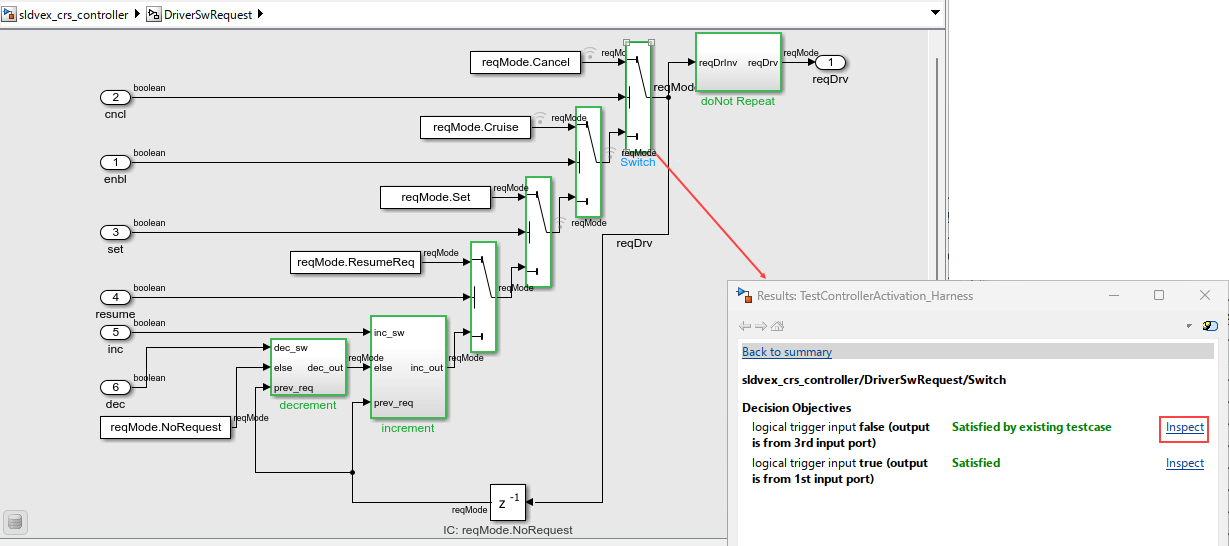
Click sldvex_crs_controller/DriverSwRequest/Switch in the Objectives section to inspect the associated objective 44.logical trigger input true (output is from 1st input port). The objective is related to cancel speed of cruise control. The Switch block is highlighted in the Simulink® canvas and shows that the associated objective is satisfied by an existing test case.

You can also use the TestControllerActivation_Harness.mat file to view the test case mapping with the objectives.

load TestControllerActivation_Harness.mat

Use Model Slicer or Simulation Data Inspector to visualize the signal values or the results.

Visualize Results Using Model Slicer

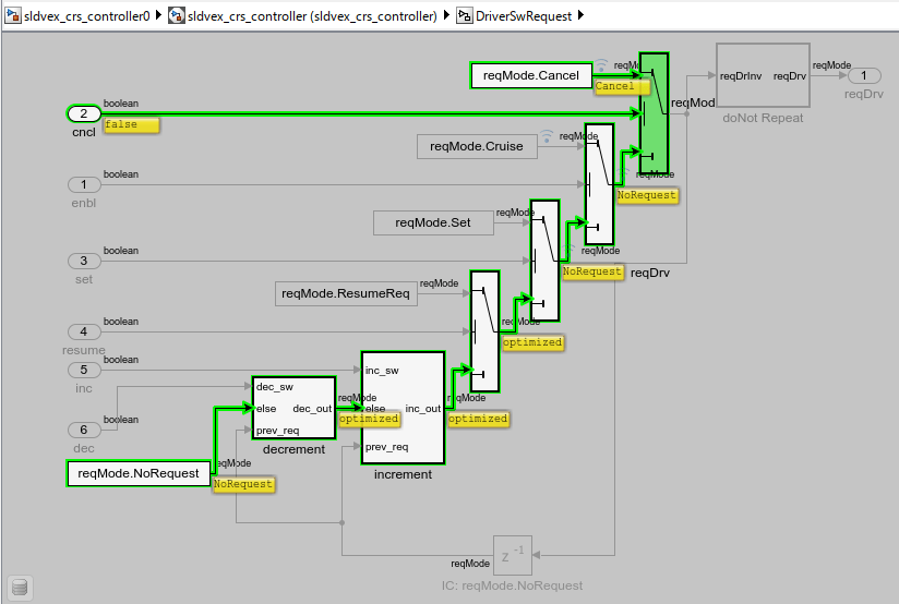
Click the Inspect button corresponding to Satisfied by existing testcase objective in the Results dialog box. Model Slicer opens and the highlighted path shows that the evaluation continues through each stage until it reaches the Cancel request logic. Since the cancel path is selected, the subsystem assigns the output value reqMode.Cancel to reqMod, which becomes the requested operating mode for the driver.

Visualize Results Using Simulink Data Inspector

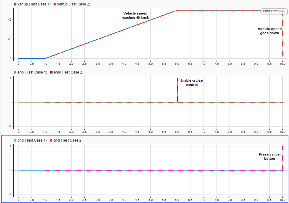
Click View Tests in Simulink Data Inspector in the Results Summary window to see the signal values of Test Case 1 and Test Case 2.

Test Case 2 first activates the cruise control by using initialization sequence from Test Case 1. The vehicle speed vehSp reaches 40 km/h, and then reduces to zero when cancel cncl signal from Test Case 2 is activated, which verifies the desired behavior of cruise control.

Running simulation in addition with Test Case 2 validates the requirement and extends the scenario to improve coverage.

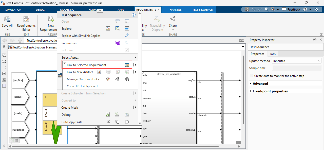
Optionally, link any requirements from the sldvex_crs_req_func_spec requirements set that are related to decrement mode behavior with Test Case 2.

See Also

|

Topics