检测整数溢出和除以零错误
以下各节描述如何分析 sldvdemo_cruise_control_fxp_fixed 模型以检测整数溢出和除以零错误。
分析模型
打开模型并检查整数溢出和除以零错误:
1.打开 sldvdemo_cruise_control_fxp_fixed 模型。
open_system('sldvdemo_cruise_control_fxp_fixed');2.在 Design Verifier 选项卡的准备部分中,从模式设置的下拉菜单中点击设置。
3.在“配置参数”对话框中,选择 Design Verifier > 设计错误检测。
4.在设计错误检测窗格中,选择:
整数溢出
除以零
5.在“配置参数”对话框的诊断 > 数据有效性窗格中,设置信号 > 溢出时绕回、信号 > 溢出时饱和。
6.点击确定保存这些设置并关闭“配置参数”对话框。
7.在模式部分中,选择设计错误检测。
8.点击检测设计错误。
分析完成后:
软件会根据分析结果突出显示模型。
Simulink® Design Verifier™ 的“结果”对话框会打开并显示分析摘要。
查看分析结果
在模型上查看结果
推导范围可以通过识别可能的信号值来帮助您了解错误的来源,您可以通过执行以下步骤来进行查看:
1.在 sldvdemo_cruise_control_fxp_fixed 模型的顶层,点击 Fixed-Point Controller 子系统。
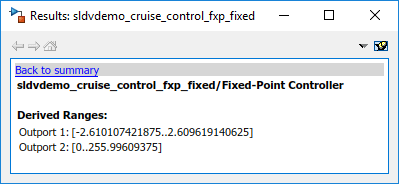
Simulink Design Verifier 的“结果”窗口会显示通过分析计算得出的 Outport 的可能信号值的推导范围:
Outport 1(油门)的值范围为 –2.6101 到 2.6096。
Outport 2(目标)的值范围为 0 到 255.9960。
2.点击 sldvdemo_cruise_control_fxp_fixed 模型的 Outport 模块以查看相同的信号边界值。
3.打开 Fixed-Point Controller 子系统。
该子系统中的两个对象用红色轮廓标出。PI Controller 子系统用绿色轮廓标出。
4.点击用红色轮廓标出的 Sum 模块,该模块为 PI Controller 子系统提供了错误输入。

该 Sum 模块可能会产生溢出错误。分析发现,有一个测试用例可能产生 Sum 模块的输出超出范围 [–128..127.9960] 的计算结果。

5.为了更充分地了解此错误,请点击为 Sum 模块提供输入的两个模块。在 Simulink Design Verifier 的“结果”窗口中,查看它们的推导范围:
Bus 模块的第三个 Outport 的范围为 [0..256]。
Switch 模块的 Outport 的范围为 [0..256]。
可以看到,对这些信号范围的求和运算可能会计算出一个超出 Sum 模块的 Outport 范围 [–128..128] 的值。
分析会报告 Sum 模块有溢出错误。分析不会传播此错误,并假定 Sum 模块的输出在任何后续计算中处于有效范围内。
6.点击用绿色轮廓标出的 PI Controller 子系统。PI Controller 子系统中的任何模块都不会产生溢出或除以零错误。当软件分析 PI Controller 子系统时,它会忽略 Sum 模块中的溢出错误,并假定该子系统的输入有效。
保持 sldvdemo_cruise_control_fxp_fixed 模型打开。在下一节中,您将创建框架模型来查看产生 Sum 模块溢出错误的测试用例。
查看框架模型
要查看演示错误的测试用例,请从 Simulink Design Verifier 的“结果”窗口生成框架模型:
1.在 sldvdemo_cruise_control_fxp_fixed 模型中,打开 Fixed-Point Controller 子系统。
2.点击用红色轮廓标出的 Sum 模块,该模块为 PI Controller 子系统提供了错误输入。
Simulink Design Verifier 的“结果”窗口会显示发生溢出错误的信息。
3.在 Simulink Design Verifier 的“结果”窗口中,点击查看反例。
软件会创建一个包含测试用例的框架模型,该测试用例具有导致此溢出错误的信号值。
在该框架模型中,将打开“信号编辑器”对话框,其中显示 Counterexample_4。
4.点击全部运行按钮以使用此测试用例对模型进行仿真。
正如预期的那样,由于 Fixed-Point Controller 子系统中 Sum 模块的溢出错误,仿真失败。
有关详细信息,请参阅管理 Simulink Design Verifier 框架模型。
查看分析报告
要查看包含有关 sldvdemo_cruise_control_fxp_fixed 模型分析报告的详细信息的 HTML 报告,请执行以下操作:
在 Simulink Design Verifier 的“结果”窗口中,点击 HTML 以查看详细分析报告。
软件会生成详细分析报告,该报告会在浏览器中打开。
对于 sldvdemo_cruise_control_fxp_fixed 模型,报告的设计错误检测目标状态章节会提供以下两类详细结果:
目标有效 - 未产生错误的模型对象
用反例证伪的目标 - 测试用例产生错误的模型对象
具有决策或条件结果的模型对象会接受死逻辑检测。有关具有决策或条件目标的模型对象完整列表的详细信息,请参阅接受覆盖率的模型对象 (Simulink Coverage)。
有关详细信息,请参阅查看结果。
注意:缺陷检查器会自动调用死逻辑、数组访问越界、除以零、整数溢出以及指定的最小值和最大值违规检查。要指定检查,请将缺陷检查器设置为 off。有关详细信息,请参阅使用优化检查检测缺陷。