Main Content

Manage Requirements and Advanced Model Checks

This example shows the how to identify potential gaps in model compliance by identifying missing requirements links, running standard and custom model checks, and performing design error detection analysis.

In this example you use:

The example model contains an adaptive cruise control algorithm that needs to be integrated into the rest of the control system software. To do this, you must ensure the algorithm meets your requirements, is compliant with modeling standards, and is free of errors.

Manage Requirements in Simulink

You can use Requirements Toolbox to view and author requirements in Simulink, and establish traceability between requirements, Simulink models, MATLAB® code, and test cases to understand the impact of a change in requirements. If your requirements are in an external tool, you need to import the requirements change into MATLAB. In this example, you work with requirements that are already imported into MATLAB using Requirements Toolbox.

View Requirements in Simulink

You can use Requirements Toolbox to view requirements traceability data directly in the Simulink canvas using a view called the Requirements Perspective.

Open the project.

prj = openProject("advancedChecksProject");

Open the model.

open_system("CruiseControl_Pod");

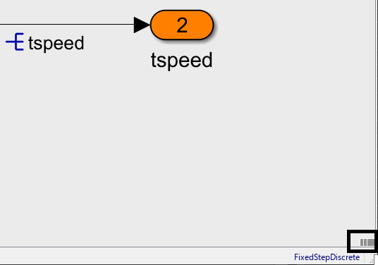
To open the Requirements Perspective, click the banner icon in the lower-right corner of the Simulink canvas.

simulinkCanvasBanner.png

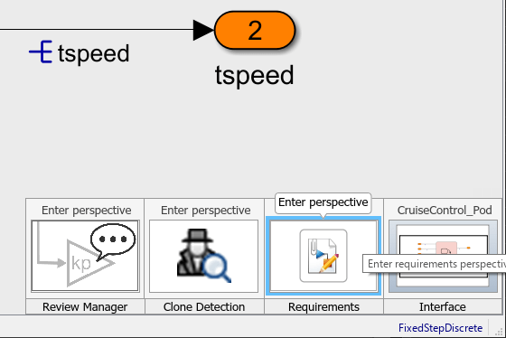
A gallery with the available perspectives opens. Click Requirements.

enterRequirementsPerspective.png

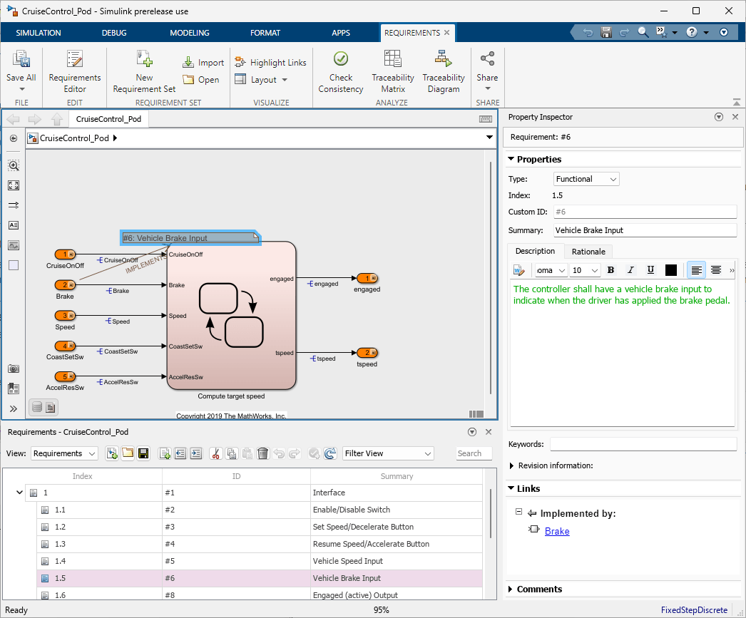
The Requirements Perspective is a view of the requirements traceability of the model. The Requirements Perspective displays:

  • Badge icons for model elements that are linked to requirements

  • The Requirements pane at the bottom of the canvas

  • The Property Inspector pane, which displays requirements traceability information

Resolve Missing Requirements Link

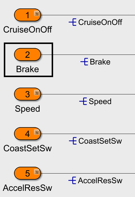
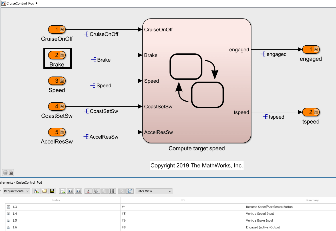
The Inport block named Brake is missing a requirements link.

missingRequirementLink.png

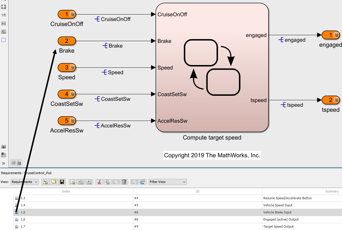
In the Requirements pane, click the arrow to expand the model requirements and the requirement set with the index 1. Click and drag the row with the index 1.5: Requirement #6: Vehicle Brake Input to the Inport block Brake.

clickAndDragRequirement.png

A Requirements badge appears on the block.

requirementsBadgeAppears.png

You can also view requirements traceability data on the model itself using requirements annotations. Click the requirements badge on the Brake block, then click Show.

requirementsBaseShowButton.png

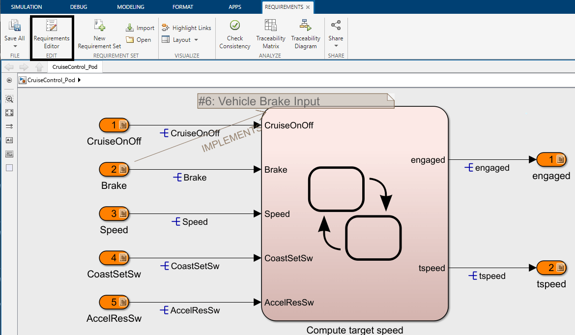
A requirements annotation for the parent requirement appears on the Simulink canvas. When you click the annotation, the requirement opens in the Property Inspector pane.

requirementsAnnotation.png

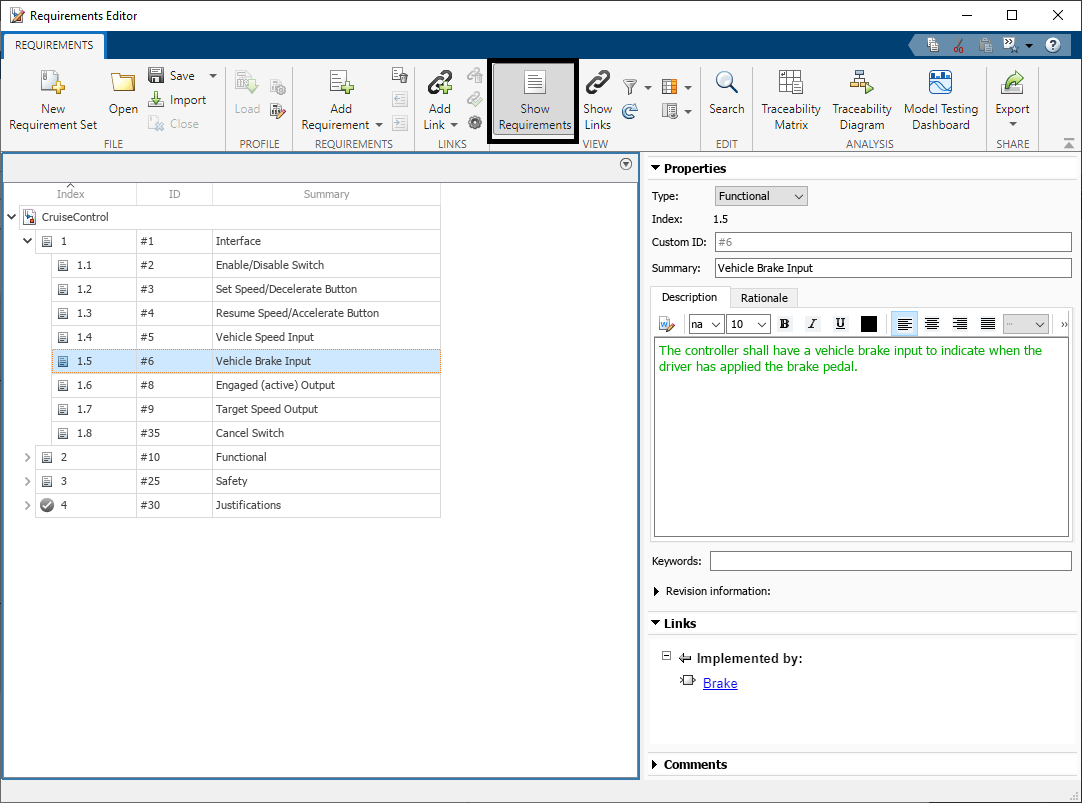
You can also view the full requirement set in the Requirements Editor by clicking on the Requirements Editor button in the Simulink Toolstrip.

requirementsEditorButton.png

In the Requirements Editor, you can view the requirements set by clicking Show Requirements in the toolstrip.

showRequirementsButton.png

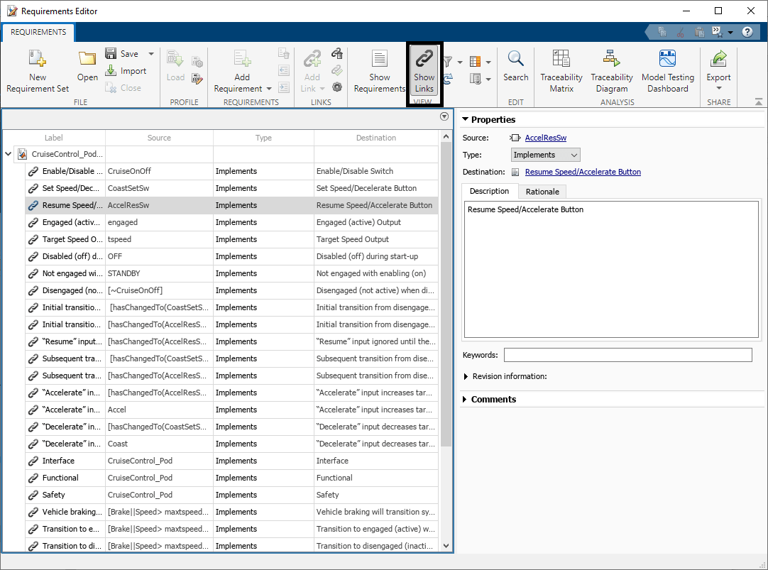
You can also view the links by clicking Show Links to open the associated link set.

showLinksButton.png

Generate a Traceability Matrix

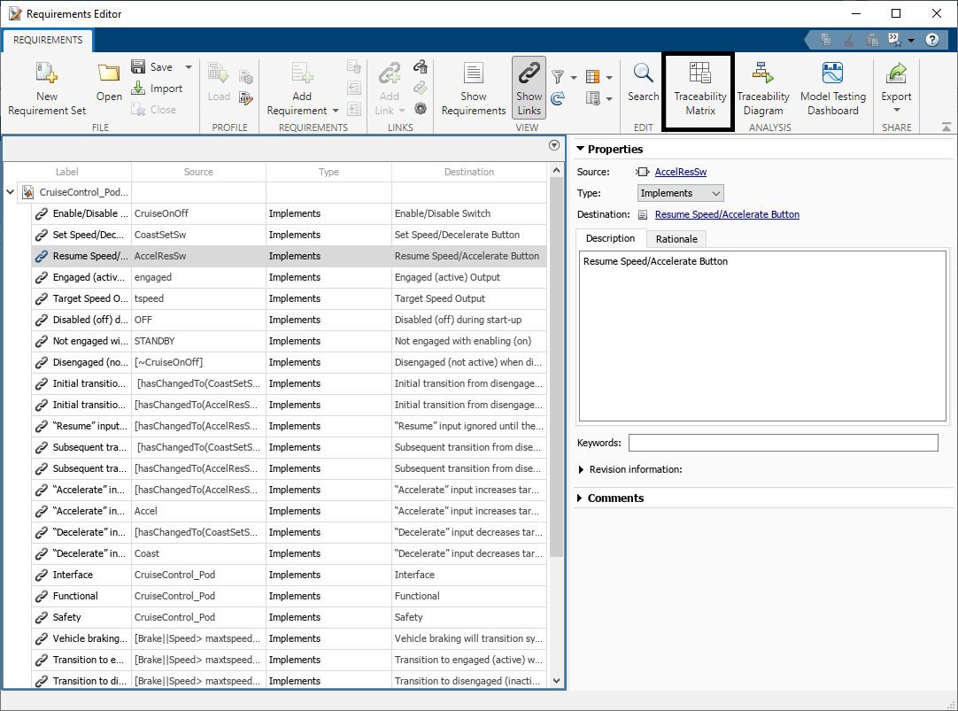
You can identify other missing requirements links in the model by creating a traceability matrix. In the Requirements Editor, click Traceability Matrix.

traceabilityMatrixButton.png

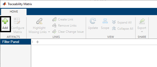
To create a traceability matrix between two artifacts, click Add.

traceabilityMatrixAdd.png

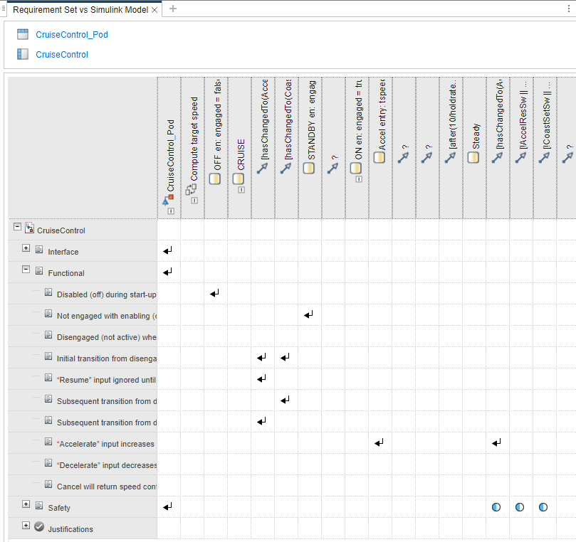
Set Left to CruiseControl.slreqx and Top to CruiseControl_Pod.slx and click Generate Matrix.

traceabilityMatrixSelectArtifacts.png

You can use the traceability matrix to analyze the traceability data further.

traceabilityMatrix.png

For more information on how to use the Traceability Matrix, see Track Requirement Links with a Traceability Matrix (Requirements Toolbox).

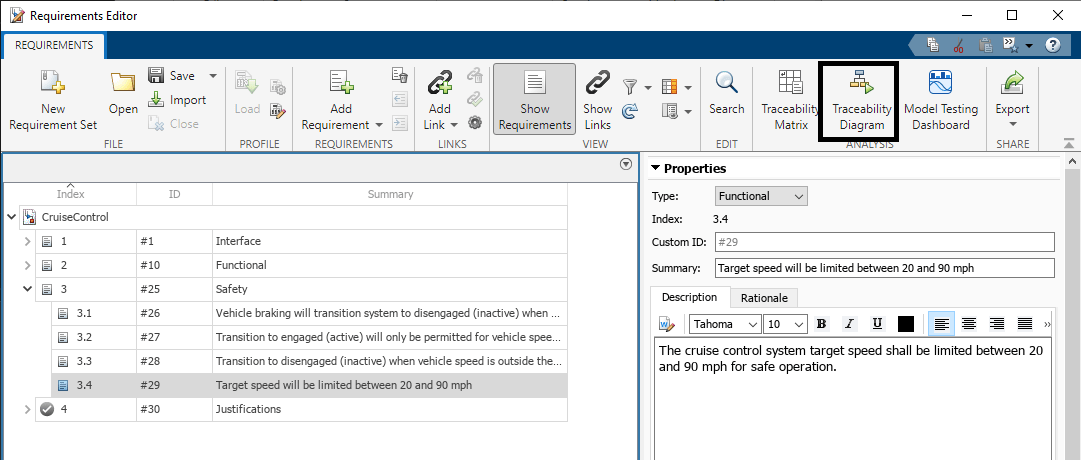
You can use a slreq.generateTraceabilityDiagram (Requirements Toolbox) to graphically visualize the traceability structure of requirements and other artifacts. In the Requirements Editor, expand the requirement with the index 3, and select the requirement with the index 3.4, Target speed will be limited between 20 and 90 mph. Click Traceability Diagram.

traceabilityDiagramButton.png

traceabilityDiagram.png

For more information about using traceability diagrams, see Visualize Links with Traceability Diagrams (Requirements Toolbox) and Assess Allocation and Impact (Requirements Toolbox).

Check Model for Standards Compliance

Designing software for general use in automobiles requires compliance with industry standards. You can use Simulink Check to verify that your model meets these standards.

Run Industry Standard Checks

You can use Simulink Check to enable edit-time checks, which run in the background while you edit your model. Simulink Check identifies issues in real time to help you find issues earlier in the model design process. You can enable edit-time checks by using the Model Advisor.

Close the CruiseControl_Pod model, and then open the CruiseControl_Model_Checks model.

close_system("CruiseControl_Pod",0);
open_system("CruiseControl_Model_Checks");

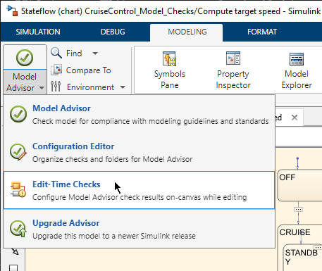
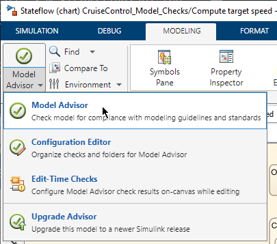
To enable edit-time checks, on the Modeling tab, click Model Advisor > Edit-Time Checks.

editTimeChecksButton.png

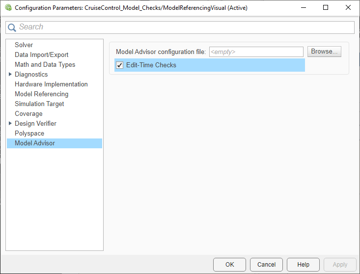
The Configuration Parameters dialog box opens to the Model Advisor pane. Select Edit-Time Checks and click OK.

editTimeChecksParameter.png

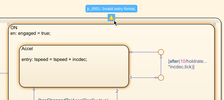
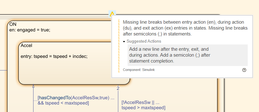
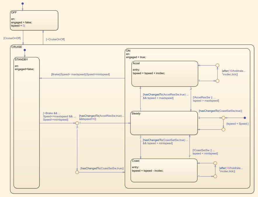
After you enable edit-time checks, check results appear on the model canvas. In the Stateflow chart, some of the states have yellow shading that indicates an issue. For example, point to the ON state and then to the yellow warning icon to see a short description of the issue flagged by the edit-time checks.

checkFlagOnState.png

Click the warning icon to see more details about the issue and suggested actions to fix the problem.

Edit-time check details state that there are missing line breaks between entry action, during action, and exit action in the states or missing line breaks after semicolons in statements. Suggested action is to add a new line after actions and semicolons.

Clear the check issues in the ON, Accel, and Coast charts by adding new lines between en or entry and the action. After adding the new lines, the yellow shading disappears.

checksClearedFromStates.png

Run Custom Checks

You can also use Simulink Check to add custom model checks, which can be helpful when you want to meet additional standards not included by default. You can add custom checks by using the Model Advisor API and the sl_customization.m file.

In this example, you use Model Advisor to run three custom checks. The custom checks are defined in sl_customization.m, and are included in the example project. You can use the sl_customization.m file used for various purposes such as changing block fonts, block colors, or Simulink window colors.

Close the model and clean up the workspace.

close_system("CruiseControl_Model_Checks",0);
clear

Refresh the Model Advisor customizations.

Advisor.Manager.refresh_customizations;

Open the CruiseControl_Model_Checks model.

open_system("CruiseControl_Model_Checks");

To open Model Advisor, in the Modeling tab, click Model Advisor > Model Advisor.

modelAdvisorButton.png

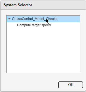
In the System Selector window, select CruiseControl_Model_Checks and click OK.

modelAdvisorSystemSelector.png

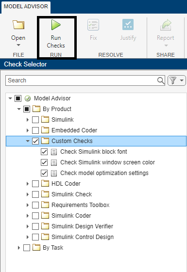
In the Model Advisor window, in the Check Selector pane, expand the By Product folder to see checks based on the products. Expand the Custom Checks folder.

This example project contains three custom checks. To run these checks, select the Custom Checks folder, then click Run Checks.

runCustomChecks.png

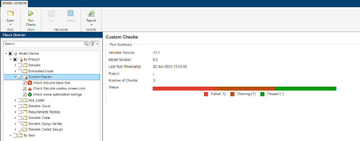
When the checks complete, the results appear in the Model Advisor window.

customCheckResults.png

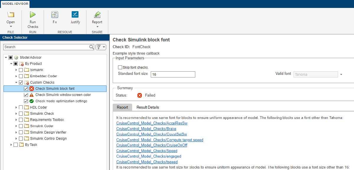
One of the checks passed, one failed, and one has a warning. Click on the failed custom check Check Simulink block font to see more details on the results.

blockFontCheckFailed.png

This check checks that all blocks use 16-point Tahoma font. The results show blocks that use a different font. You can clear these check failures by changing the block fonts and font sizes in the model to Tahoma by clicking a block and changing the font and font size using the Format tab in the Simulink Toolstrip.

For more information about authoring custom edit-time checks, see ModelAdvisor.EdittimeCheck class and Define Edit-Time Checks to Comply with Conditions That You Specify with the Model Advisor.

Check Model for Design Errors

Simulink Design Verifier is a static analysis tool that uses formal methods to detect errors. It checks for several types of design errors, including division-by-zero, integer overflow, and dead logic. In this example, you analyze the model for division-by-zero errors. Division-by-zero occurs when a zero is used in the denominator of a division operation, which causes a run-time error. In traditional, simulation-based testing, it can be difficult to create tests that reveal division-by-zero errors.

Enable Design Error Detection Mode

Enable division-by-zero detection in Simulink Design Verifier

Close the model and clean up the workspace.

bdclose all
clear

Open the CruiseControl_DivByZero model.

open_system("CruiseControl_DivByZero")

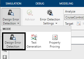
In the Apps tab, under Model Verification, Validation, and Test, click Design Verifier. In the Mode section, ensure that Design Error Detection mode is enabled.

designErrorDetectionButton.png

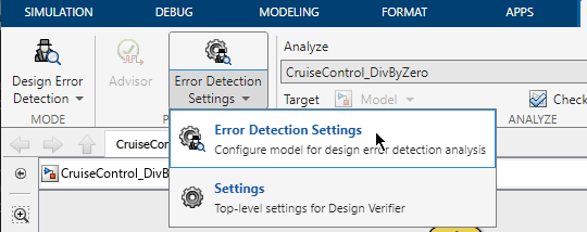
To open the error detection settings, on the Design Verifier tab, click Error Detection Settings > Error Detection Settings.

designErrorDetectionSettings.png

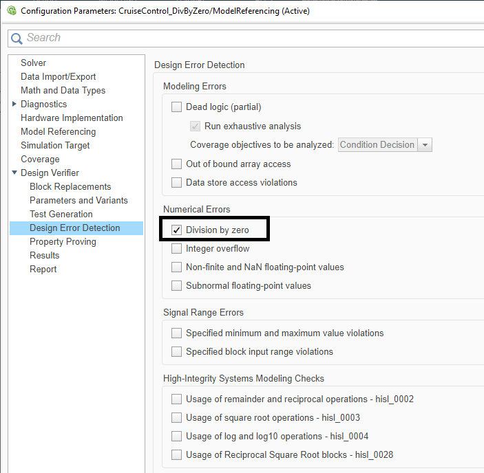
Select Division by zero and click Apply.

divisionByZeroParameter.png

Use Parameters in Analysis

The model has several tunable parameters, each with its own range. It is recommended to include the parameter ranges in the analysis because an inadvertent change in a parameter value can cause a run-time error. When you set a parameter range, Simulink Design Verifier treats the parameter like a signal that has its own range, instead of as a constant.

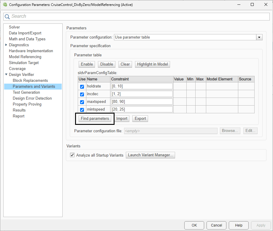
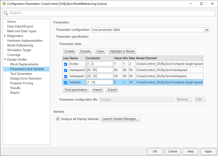
In the Configuration Parameters Dialog Box, in the left pane, under Design Verifier, click Parameters and Variants. The parameter table is enabled by default. Simulink Design Verifier uses the specified parameter configuration during analysis. To find new parameters defined in the model, or to view more details about the parameters listed, click Find parameters.

findParameters.png

When you click Find parameters, the table populates with the tunable parameters in the model. Click OK.

Run Analysis to Check for Design Errors

In the Simulink Toolstrip, on the Design Verifier tab, click Detect Design Errors.

detectDesignErrorsButton.png

Analyze Results

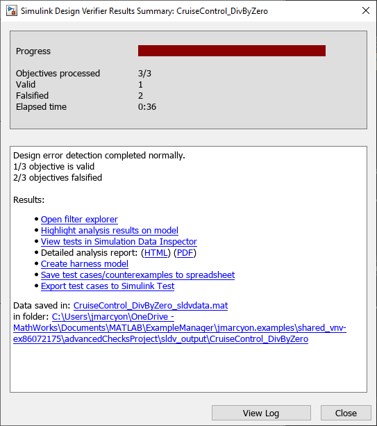
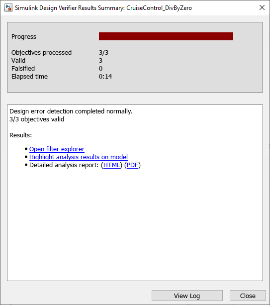
When the analysis completes, the Simulink Design Verifier Results Summary window opens.

designErrorDetectionResultsSummary.png

Simulink Design Verifier finds two instances where a division-by-zero may occur and reports them as falsified objectives. Because the model contains two division operations, Simulink® Design Verifier™ identifies two falsified objectives.

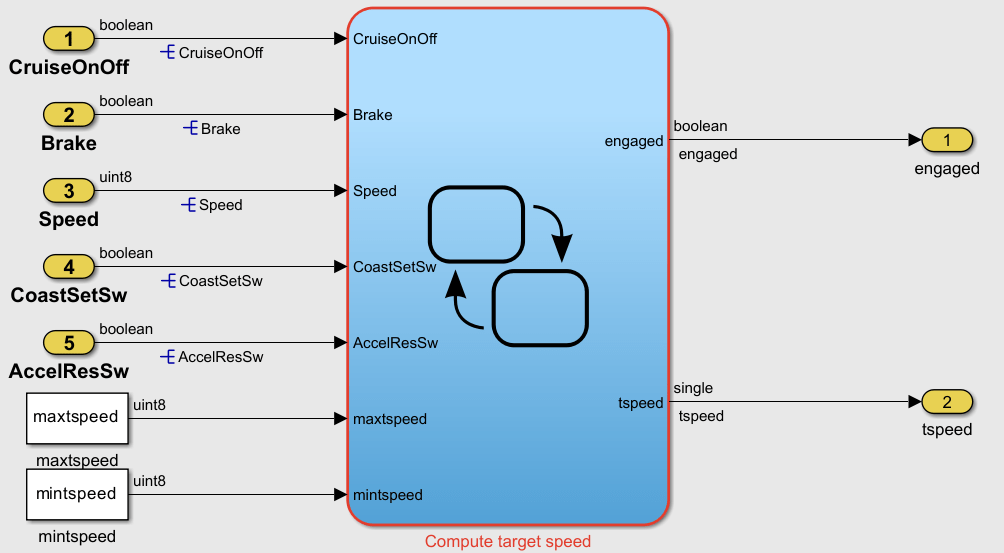
Click Highlight analysis results on model to highlight the results in the model. The Compute target speed Stateflow chart has a red highlight.

designErrorDetectionModelHighlight.png

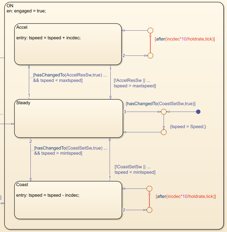
Double-click on the Compute target speed Stateflow chart. Inside chart, there are two transitions in the ON state highlighted red.

designErrorDetectionTransitionHighlight.png

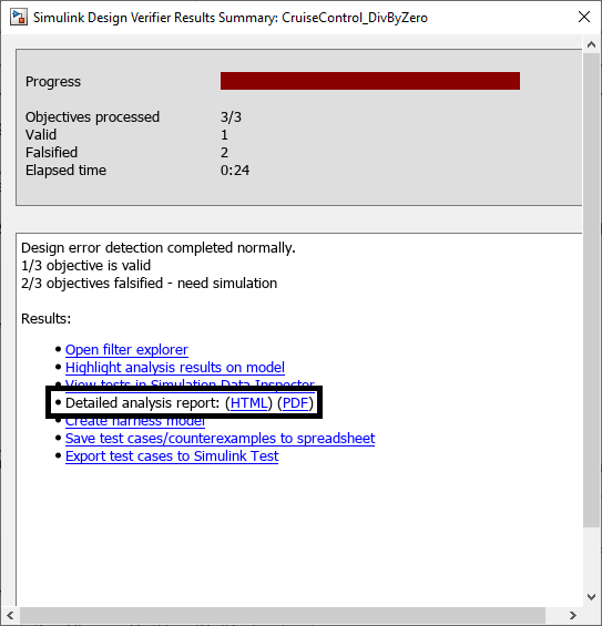
The design error relates to the holdrate parameter, which both transitions use. To see more information about how Simulink Design Verifier uses this parameter in the analysis, see the detailed report. In the Simulink Design Verifier Results Summary window, next to Detailed analysis report, click HTML.

resultsSummaryDetailedReport.png

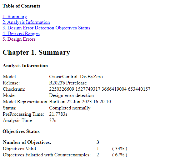
In the HTML report, click the Design Errors link in the table of contents.

designVerifierReportTOC.png

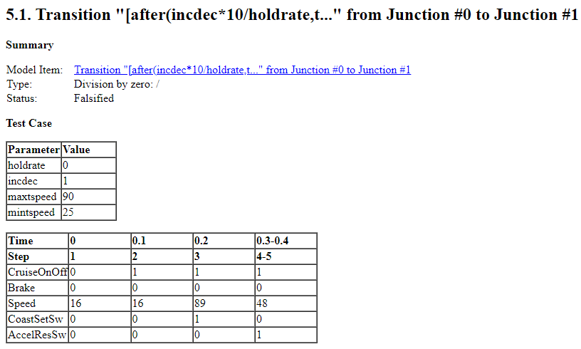
Look at the first design error in section 5.

designVerifierReportTransition1.png

Simulink Design Verifier created a test case that shows how a division-by-zero could occur. The value of holdrate is set to 0 in the test case because the minimum value of the holdrate parameter in the range table is 0. Fix the issue by changing the minimum value to 1.

holdrate.Min = 1;

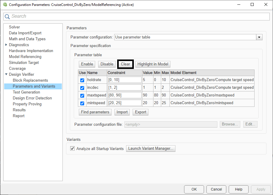
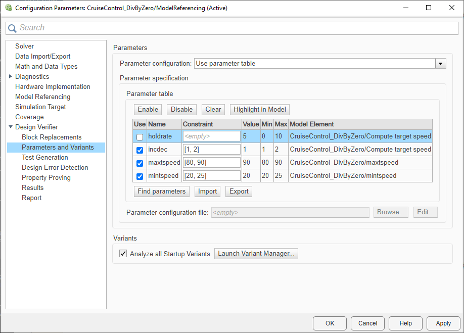
Save the model, then navigate to the Parameters And Variants pane in the Configuration Parameters dialog box. To tell Simulink Design Verifier to look for the new parameter value for holdrate, select the holdrate row and click Clear.

parametersClearButton.png

parametersHoldRateCleared.png

To update the parameter table and fetch the new minimum value for holdrate, click Find parameters.

parametersHoldRateMin1.png

Now re-run the design error detection analysis by clicking Detect Design Errors. The division-by-zero is no longer possible.

designVerifierResultsComplete.png

See Also

(Requirements Toolbox) |

Related Topics