Belt-Cable Spool
Source and sink of cord in a pulley system
Libraries:
Simscape /
Multibody /
Belts and Cables
Description
The Belt-Cable Spool block represents a cylindrical drum on which to wind (and from which to unwind) the cord of a pulley system. The spool marks an end to the cord and the point at which a motor or other power source often pulls on a load. A Belt-Cable End block generally marks the second tip of the cord, to which the load itself is commonly attached. Depending on whether it is winding or unwinding, the spool can behave as an infinite source of cord or as an infinite sink of the same.
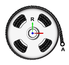
The spool serves as an interface between the belt-cable domain specific to pulley systems and the frame domain general to all other multibody components. The belt-cable port (A) identifies the tip of the cord to be wound on the spool and the relative placement of that tip within a pulley system. A frame port (R) identifies the reference frame of the spool and its placement in the broader multibody model.
The degrees of freedom of the spool are a function of the joint by which the spool connects to other components. It is common for a revolute joint to provide those degrees of freedom; they reduce in this case to rotation about a single axis (that of the spool). Actuation inputs, specified directly through the joint by means of torque or motion signals, serve to drive the spool and to wind (or unwind) the cord.
The cord enters and exits the drum in tangency with the drum circumference. Consistent with the right-hand rule, the winding is in a counterclockwise direction about the rotation axis of the drum. This axis is by definition the z-axis of the local reference frame (R). To reverse the direction of the winding, you must flip the local reference frame so that the z-axis points in the opposite direction—for example, by the application of a frame rotation through a Rigid Transform block.
The surface of the spool (smooth or grooved) is not considered in the model. In addition, the cord is assumed to wrap around the spool in a circle that is of constant radius (that of the pitch circle) and coplanar with the transverse cross section of the winch. Changes in spool radius due to winding are ignored.
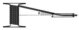
By default, the cord can enter and exit a spool at an angle to its center plane (θ in the figure). This angle can vary during simulation—for example, due to translation of the spool on a prismatic joint. While the contact point is always in the center plane of the spool, the spool can move when mounted on a joint. The cord can also be constrained to enter and exit the spool in its center plane. Whether this constraint is enforced depends on the settings of the Belt-Cable Properties block.
The inertia of the spool and of the cord wound on it are also ignored. To capture the inertia of a spool of fixed mass, use the Cylindrical Solid or Inertia block. Consider the Cylindrical Solid block if solid geometry is important in the model. To capture the variable mass properties of a cord as it winds on, and unwinds from, the spool, use a block from the Variable Solids library—for example Variable Cylindrical Solid or General Variable Mass.
Examples
Ports
Frame
Belt-Cable
Parameters
Extended Capabilities
Version History
Introduced in R2018a

