Convert CAD Assembly into Simscape Multibody Model
You can create a Simscape™ Multibody™ model by using a CAD assembly created by applications, such as Onshape®, Autodesk® Inventor®, PTC® Creo™, or SolidWorks®. The conversion has two steps. First, the export step converts a CAD assembly into an XML file and a set of geometry files, and then the import step creates an equivalent Simscape Multibody model by using the exported files. The import step also generates an M-file that contains the data to specify all the blocks in the model.

Export a CAD Assembly
The Simscape Multibody Link CAD plug-in provides one means to export a CAD assembly in a valid XML format. The plug-in is compatible with three CAD applications: Autodesk Inventor, PTC Creo, and SolidWorks. The plug-in generates the XML multibody description file and all the geometry files required for visualization in the converted model.
You can also use the smexportonshape function to export a CAD
assembly from Onshape. For more information on exporting CAD models from Onshape, see Onshape Import.
If the CAD assembly is created by other CAD applications, to generate the multibody description and part geometry files, you can create a program that uses the CAD API and Simscape Multibody XML schema. This task requires knowledge of XML documents, XSD schema definitions, and CAD APIs. For the XSD schema definitions, see the schema website. For an example program built on the SolidWorks CAD API, see MATLAB Central.
You may be able to export a CAD assembly in URDF format and use the URDF file to create the equivalent Simscape Multibody model if your CAD application has a URDF converter. Note, however, that the URDF specification forbids closed-chain model topologies, such as four-bar linkages and gear assemblies. For more information, see Import URDF Models.
If the Simscape Multibody Link plug-in cannot export a part geometry file or translate a CAD constraint set, the software returns an error message. The error message identifies the bodies with missing geometry files and any unsupported constraints. You can still import the generated XML multibody description file into Simscape Multibody, but the resulting model may not accurately represent the original CAD assembly.
Import a Model
You can create an equivalent Simscape
Multibody model by using the smimport function with the files generated in the export step. The
function parses the XML file, extracts the necessary data, and reconstructs the assembly
in the Simscape
Multibody environment by using Simscape
Multibody blocks for the CAD assembly's bodies, constraints, and joints. For
step-by-step instructions on how to import a CAD assembly model via its XML file, see
Import a CAD Assembly Model.
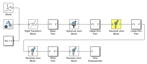
Converted Multibody Model
By default, the created model preserves the structural hierarchy of the source CAD
assembly. If the CAD assembly has subassemblies and parts, the
smimport function converts them into Simscape
Multibody subsystems. For instance, in the Import a CAD Assembly Model
example, the grip subassembly has seven parts.

After the conversion, the grip contains seven subsystems that represent the corresponding parts.

To represent the parts of a CAD assembly, the smimport function uses the Simscape
Multibody solid blocks to specify the geometries, inertias, and colors of bodies
and uses Rigid
Transform blocks to specify the locations and orientations. For
example, the figure shows the upper arm of a robotic assembly.
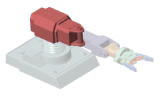
The converted model consists of one solid block connected to a pair of Rigid Transform blocks. The solid block models the geometry and inertial properties of the arm, and the Rigid Transform blocks specify the location and orientation of the arm with respect to the base and lower arm bodies.

If an exported geometry file is invalid or missing, after the conversion, the corresponding body does not display in the Simscape Multibody visualization utility.
During the conversion, the smimport function converts the
joints, constraints, and mates of the CAD assembly into combinations of Simscape
Multibody joint and constraint blocks. For instance, in the robotic arm example,
the constraints between the upper and lower arms are converted into a Revolute Joint block. This joint block connects the subsystems
that represent the upper and lower arms.
If a CAD assembly contains an unsupported constraint combination between bodies, Simscape Multibody returns a warning message that identifies the affected bodies and their connection frames.
Warning: The set of constraints between the Upper Arm Part and Lower Arm Part
could not be mapped to a joint. A rigid connection has been added between port F
of the Upper Arm Part and port F1 of the Lower Arm Part for these constraints.
Also, Simscape Multibody replaces the constraint with a rigid connection.

The rigid connection can take the form of a direct frame connection line, Rigid Transform block, or Weld Joint block.
Block Data
During the conversion, the smimport function generates an
M-file that stores the data of all the blocks in the Simscape
Multibody model. The block data is parameterized in terms of MATLAB® variables. These variables are stored in structure arrays named after
the block types. The structure arrays are nested in a parent data structure named
smiData or a custom string that you specify.
Consider a converted model with a data structure named smiData.
If the model contains Revolute Joint blocks, the
parameter data for these blocks is the structure array
smiData.RevoluteJoint. This structure array contains a number
of data fields, each corresponding to a different block parameter.
The structure array fields are named after the block parameters. For example, the
position state target data for the Revolute Joint
blocks is in a field named Rz_Position_Target. If the model has
two Revolute Joint blocks, this field contains two
entries—smiData.RevoluteJoint(1).Rz_Position_Target
and smiData.RevoluteJoint(2).Rz_Position_target.
Each structure array index corresponds to a specific block in the converted model.
The index assignments can change if you regenerate an M-file from an updated XML
multibody description file. The smimport function checks the
prior data file, when specified, to ensure the index assignments remain the same.
See Update Converted Model.
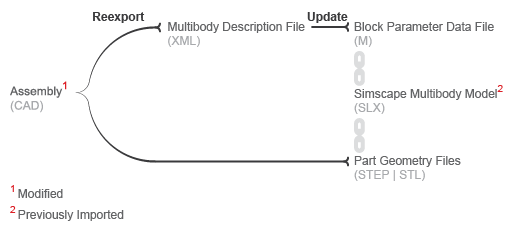
Update Converted Model
To reflect the changes of the source CAD assembly, you can use the smimport with ImportMode=modelAndDataFile or
ImportMode=dataFile argument. When using the
ImportMode=modelAndDataFile argument, the
smimport function updates both the converted model and
M-File.
When using the ImportMode=dataFile argument, the
smimport function updates only the M-file. The
smimport function uses the prior M-file to keep the mapping
between structure array indices and blocks consistent. The function does not update
the block diagram. If you add or delete bodies in the source CAD assembly, you must
manually add or delete the corresponding blocks in the previously converted
multibody model. Before regenerating an M-file, you must export a new XML multibody
description file from the updated CAD assembly. The smimport
function uses the data in the new XML file to generate the new M-file.
Simplify Model Topology
You can simplify the topology of the converted model by using the
ModelSimplification argument of the
smimport function. You can set this argument to:
Use
bringJointsToTopto group each set of rigidly connected parts into a new subsystem and promote all joints to the top level of the model hierarchy.Use
groupRigidBodiesto group rigidly connected parts into subsystems (and leave joints in their original places in the model hierarchy).Use
Noneto import the model as is, without simplification.
Use bringJointsToTop or groupRigidBodies if
the source CAD assembly has many rigidly connected components, such as nuts and
bolts, that you prefer to group together, to more intuitively grasp the key
components of the model at a glance of the block diagram.
Use bringJointsToTop if the source CAD assembly has joints
inside subassemblies and you prefer to expose them at the top level, to work with
joint actuations and sensing signals without having to search for the joints inside
different subsystems.
Note that model simplification is available only for CAD assemblies. URDF models have flat topologies with little need for simplification.