URDF Primer
Unified Robotics Description Format, URDF, is an XML specification used in academia and industry to model multibody systems such as robotic manipulator arms for manufacturing assembly lines and animatronic robots for amusement parks. URDF is especially popular with users of Robotics Operating System, ROS. You can import URDF models into the Simscape™ Multibody™ environment to create a multibody dynamics model for simulation, analysis, or control design tasks. See the Humanoid Robot featured example for a simple use case.
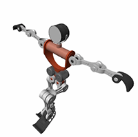
Humanoid Robot URDF Model

URDF Elements and Attributes
Like other types of XML files, URDF files comprise various XML
elements, such as <robot>, <link>, <joint>,
nested in hierarchical structures known as XML trees. For example,
the <link> and <joint> elements
are said to be children of the <robot> element
and, reciprocally, the <robot> element the
parent of the <link> and <joint> elements.
<robot>
	<link>
		...
	</link>
	<link>
		...
	</link>
	<joint>
		...
	</joint>
</robot>
Child elements, such as <link> and <joint> under <robot>,
can in turn have child elements of their own. For example, the <link> element
has the child elements <inertial> and <visual>.
The <visual> element has the child elements <geometry> and <material>.
And the <material> element has the child
element <color>. Such chains of child elements
are essential to define the properties and behavior of the parent
elements.
<robot>
	<link>
		<inertial>
			...
		</inertial>
		<visual>
			<geometry>
				...
			</geometry>
			<material>
				<color />
			</material>
		</visual>
	</link>
	...
</robot>
In addition to child elements, the XML elements in a URDF model
can have attributes. For example, the <robot>, <link>,
and <joint> elements all have the attribute <name>—a
string that serves to identify the element. The <color> element
has the attribute rgba—a numeric array with
the red, green, blue, and alpha (or opacity) values of the link color.
Attributes such as these help to completely define the elements in
the model.
<robot name = "linkage">
	<link name = "root link">
		<inertial>
			...
		</inertial>
		<visual>
			<geometry>
				...
			</geometry>
			<material>
				<color rgba = "1 0 0 1" />
			</material>
		</visual>
	</link>
	...
</robot>
XML Hierarchies and Kinematic Trees
URDF links connect through joints in hierarchical structures
not unlike those formed by nesting XML elements in a URDF file. <joint> elements
enforce these hierarchies through <parent> and <child> elements
that identify one link as the parent and the other as the child. Parent
links can themselves be children—and child links parents—of
other links in the model.
<parent> and <child> Joint
Elements
<robot name = "linkage">
	<joint name = "joint A ... >
		<parent link = "link A" />
		<child link = "link B" />
	</joint>
	<joint name = "joint B ... >
		<parent link = "link A" />
		<child link = "link C" />
	</joint>
	<joint name = "joint C ... >
		<parent link = "link C" />
		<child link = "link D" />
	</joint>
</robot>
You can visualize the connections between links using a schematic known as a connectivity graph. The figure shows an example. Circles denote links and arrows denote joints. The arrow roots identify the parent nodes and the arrow tips the child nodes. The connectivity graph reveals the topology of the underlying model—here a simple kinematic tree with two branches.
Connectivity Graph of a Kinematic Tree

Model topology is important in URDF. The connectivity graph
of a model can take the shape only of a kinematic tree—a kinematic
chain, branched or unbranched, that is always open. Kinematic loops,
each a closed chain formed by joining the ends of an otherwise open
chain, are disallowed. This restriction impacts how <link> elements
can connect in a URDF model.
The restriction translates to the following rule: no <link> element
can serve as a child node in more than one <joint> element.
Put another way, no <link> element can have
more than one parent element in the model’s connectivity graph.
Only the root link, that at the origin of the connectivity graph,
can have a number of parent nodes different from one (zero). Only
one root link is allowed in a model.
Kinematic Loop URDF Example
<robot name = "linkage">
	<joint name = "joint A ... >
		<parent link = "link A" />
		<child link = "link B" />
	</joint>
	<joint name = "joint B ... >
		<parent link = "link A" />
		<child link = "link C" />
	</joint>
	<joint name = "joint C ... >
		<parent link = "link C" />
		<child link = "link D" />
	</joint>
	<joint name = "joint D ... >
		<parent link = "link B" />
		<child link = "link D" />
	</joint>
</robot>
The code declares a link, link D, as a child
node in two <joint> elements, joint
C and joint D. The link D element
has two parents and forms a kinematic loop. The model violates the
URDF connection rules and is invalid. The figure shows the connectivity
graph of the model.
Connectivity Graph of a Kinematic Loop

Required and Optional URDF Entities
Not all elements and attributes listed in the URDF specification
are required. Some, like <inertial> under <link>,
are optional. The following code shows the various elements and attributes
that you can use, with those that are optional colored green.
Elements and attributes shown as required inside optional elements are so only if the optional elements are used. The default values of optional attributes are shown in parentheses and in italic font. Note that this code is included only as a reference and that it does not represent a valid URDF model. Ellipses (“...”) are invalid in URDF models and are used merely to break long lines of code for ease of viewing.
<robot name>
	<link name>
		<inertial>
			<origin xyz("0 0 0") rpy("0 0 0") />
			<mass value />
			<inertia ixx iyy izz ixy ixz iyz />
		</inertial>
		<visual name>
			<origin xyz("0 0 0") rpy("0 0 0") />
			<geometry>
				<box size />
				<cylinder radius length />
				<sphere radius />
				<mesh filename scale("1") />
			</geometry>
			<material name>
				<color rgba("0.5 0.5 0.5 1") />
				<texture filename />
			</material>
		</visual>
		<collision name>
			<origin xyz("0 0 0") rpy("0 0 0") />
			<geometry>
				<box size />
				<cylinder radius length />
				<sphere radius />
				<mesh filename scale("1") />
			</geometry>
		</collision>
	</link>
	<joint name type>
		<origin xyz("0 0 0") rpy("0 0 0") />
		<parent link />
		<child link />
		<axis xyz("1 0 0") />
		<calibration rising />
		<calibration falling />
		<dynamics damping("0") friction("0") />
		<limit† lower† upper† effort velocity />
		<mimic joint multiplier("1") offset("0") />
		<safety_controller soft_lower_limit("0") ...
		... soft_upper_limit("0") k_position("0") k_velocity("0") />
	</joint>
</robot>
†Required for <joint> elements
of type prismatic and revolute only.
Create a Simple URDF Model
As an example, create a URDF model of a double pendulum. In your text editor of choice, create
a file with the code shown below and save the file as
DoublePendulum.urdf in a convenient folder. Include
the file extension in the file name. A separate example shows how to import
this model into the Simscape
Multibody environment (see Import a Simple URDF Model).
<robot name = "linkage">
	<!-- links section -->>
	<link name = "link A">
		<inertial>
			<origin xyz = "0 0 0" />
			<mass value = "0.5" />
			<inertia ixx = "0.5" iyy = "0.5" izz = "0.5"
ixy = "0" ixz = "0" iyz = "0" />
		</inertial>
		<visual>
			<origin xyz = "0 0 0" />
			<geometry>
				<box size = "0.5 0.5 0.1" />
			</geometry>
			<material name = "gray A">
				<color rgba = "0.1 0.1 0.1 1" />
			</material>
		</visual>
	</link>
	<link name = "link B">
		<inertial>
			<origin xyz = "0 0 -0.5" />
			<mass value = "0.5" />
			<inertia ixx = "0.5" iyy = "0.5" izz = "0.5"
	ixy = "0" ixz = "0" iyz = "0" />
		</inertial>
		<visual>
			<origin xyz = "0 0 -0.5" />
			<geometry>
				<cylinder radius = "0.05" length = "1"  />
			</geometry>
			<material name = "gray B">
				<color rgba = "0.3 0.3 0.3 1" />
			</material>
		</visual>
	</link>
	<link name = "link C">
		<inertial>
			<origin xyz = "0 0 -0.5" />
			<mass value = "0.5" />
			<inertia ixx = "0.5" iyy = "0.5" izz = "0.5"
	ixy = "0" ixz = "0" iyz = "0" />
		</inertial>
		<visual>
			<origin xyz = "0 0 -0.5" />
			<geometry>
				<cylinder radius = "0.05" length = "1"  />
			</geometry>
			<material name = "gray C">
				<color rgba = "0.5 0.5 0.5 1" />
			</material>
		</visual>
	</link>

	<!-- joints section -->>
	<joint name = "joint A" type = "continuous">
		<parent link = "link A" />
		<child link = "link B" />
		<origin xyz = "0 0 -0.05" />
		<axis xyz = "0 1 0" />
	</joint>
	<joint name = "joint B" type = "continuous">
		<parent link = "link B" />
		<child link = "link C" />
		<origin xyz = "0 0 -1" />
		<axis xyz = "0 1 0" />
		<dynamics damping ="0.002" />
	</joint>
</robot>
About the URDF Model
The code defines a multibody model named linkage.
The model contains three links, named link A, link
B and link C, that connect via two joints,
named joint A and joint B. The <parent> and <child> elements
of the joints identify how the links connect to each other: link
A connects to link B and link
B connects to link C. link A has
no parent link—that is, it appears in <joint> elements
as a child element only—and is therefore the root link.
The <inertial> element of link
A defines the mass and moments of inertia (ixx, iyy, izz)
of the link. The products of inertia (ixy, ixz,
and iyz) are unspecified and have the URDF default
value of zero. The visual element of link
A defines the geometry type and material color for use in
the model visualization. The geometry in this case is a box with width
and thickness of 0.5 m and height of 0.1 m.
The <origin> elements of the link <inertial> and <visual> specify
the transforms from the link reference frame to the inertial and visual
reference frames. Similar elements apply to link B and link
C.
The type attribute of the <joint> elements
defines the joints as continuous—a type of revolute joint without
motion limits. The <origin> element specifies
the location of the joint relative to the reference frame of the parent
link element. For example, the <origin> element
of joint A offsets the joint 0.05 m
along the -Z axis relative to the origin of the link
A reference frame. The axis element nested
inside each joint element defines the rotational
axis of the joint as the Cartesian vector [0, 1, 0],
or +Y.
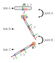
The figure shows the components of the model—the links and joints—and the various frames they contain. R denotes a link reference frame, I a link inertial frame, and V a link visual frame. J denotes a joint reference frame—by definition held coincident with the reference frame of the child link. The inertial and visual frames are offset to the centers of the links and the joint frames to their lower edges.
Double-Pendulum Model Components

Obtaining URDF Models to Import
You can, but generally do not have to, manually create your own URDF files. For more complex models, it can be preferable to obtain URDF files from other sources. Robotics manufacturers and consultants often provide URDF models for their robotic systems. CAD applications such as SolidWorks® and PTC® Creo™ support URDF exporters that convert your CAD assemblies into URDF models. Consider these options when working with complex robotics models that may not be simple to create manually.