Main Content

Video Capture HDMI

Import live video frames from HDMI FMC card on Zynq-based hardware

Since R2023a

Add-On Required: This feature requires the SoC Blockset Support Package for AMD FPGA and SoC Devices add-on.

  • Video Capture HDMI block

Libraries:
SoC Blockset Support Package for AMD FPGA and SoC Devices / MPSoC / ZCU102
SoC Blockset Support Package for AMD FPGA and SoC Devices / MPSoC / ZCU106
SoC Blockset Support Package for AMD FPGA and SoC Devices / Zynq-7000 / PicoZed
SoC Blockset Support Package for AMD FPGA and SoC Devices / Zynq-7000 / ZC702
SoC Blockset Support Package for AMD FPGA and SoC Devices / Zynq-7000 / ZC706
SoC Blockset Support Package for AMD FPGA and SoC Devices / Zynq-7000 / ZedBoard

Description

The Video Capture HDMI block captures video frames from a Zynq®-based board that has an HDMI FMC card, and imports the frames into your Simulink® model. The reference design programs the FPGA with an image that includes data path multiplexers, video format conversions, and a video test pattern generator (TPG). You can control these data path and conversion options from the Video Capture HDMI block.

Points A and B in the diagram show the options for capturing video into Simulink or an ARM® processor. The FPGA user logic section is the IP core that you generate from your design using HDL Workflow Advisor. You can capture the input video before the FPGA user logic, or the output video after the FPGA user logic. If you enable the bypass of the FPGA user logic, or if you have not generated any FPGA user logic, the two capture locations show the same data.

The video data is a pixel stream on the FPGA, but when you import the video into Simulink, the stream converts to frame-based video.
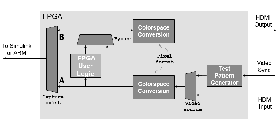
FPGA design diagram showing the HDMI video input is converted to the specified format and routed through the FPGA user logic.

The HDMI reference designs require the same video resolution and color format for the entire data path. The resolution you select for the Video Capture HDMI block must match that of your camera input. The design you target to the FPGA user logic must not modify the frame size or format of the data.

When you use this block in a model deployed with the default FPGA image, you can change the video format that the reference design captures to the ARM processor and therefore the format of the video frames imported to Simulink.

The HDL Workflow Advisor generates a software interface model that contains the Video Capture HDMI block. The parameter settings of the generated block match the settings of the Video Capture HDMI block in your original model. You can change the input video resolution, switch between HDMI input or an on-chip test pattern generator, and enable an optional bypass of the user logic section of the FPGA. When you change a parameter, the block writes an AXI-Lite register on the board.

You can also deploy this block to an ARM processor to capture the video from the FPGA user logic into the ARM for further processing. When you use the block this way, the settings on the block must match those of the deployed FPGA image.

To use this block in the generated software interface model, or to create your own model to target an ARM processor, you must have the Embedded Coder® product and the Embedded Coder Support Package for AMD SoC Devices.

Examples

Limitations

  • To use this block, in the hardware setup, set Hardware Board to one of the supported Xilinx® boards and set Add-on Card to FMC-HDMI-CAM. You can find the supported boards in the Libraries list at the top of this page.

  • Use the IP core workflow to generate HDL code. This block does not support using the SoC Builder tool. For more information on workflows, see SoC Generation Workflows.

    In the HDL Workflow Advisor tool, select one of these supported platforms and one of these supported reference designs.

    Target PlatformReference Design
    • ZCU106 FMC-HDMI-CAM

    • ZCU102 FMC-HDMI-CAM

    • PicoZed FMC-HDMI-CAM

    • ZC702 FMC-HDMI-CAM

    • ZC706 FMC-HDMI-CAM

    • ZedBoard FMC-HDMI-CAM

    • RGB

    • Y only

    • YCbCr 4:2:2

    • RGB AXI4-Stream Video Interface

    • Y only AXI4-Stream Video Interface

    • YCbCr 4:2:2 AXI4-Stream Video Interface

    You can also use the HDL Workflow Advisor to generate a software model for running in external mode.

Ports

Output

expand all

The block returns one matrix for each color component of the input video. The dimensions of the Y matrix match the frame size. The dimensions of the Cb and Cr matrices are height-by-width/2 because the 4:2:2 format alternates Cb and Cr values for each pixel in the frame.

Dependencies

To enable these ports, set Pixel format to YCbCr 4:2:2.

Data Types: single | double | int8 | int16 | int32 | int64 | uint8 | uint16 | uint32 | uint64 | Boolean | fixed point

The block returns one matrix for each color component of the input video. The dimensions of each matrix match the frame size.

Dependencies

To enable these ports, set Pixel format to RGB and Image signal to Separate color signals.

Data Types: single | double | int8 | int16 | int32 | int64 | uint8 | uint16 | uint32 | uint64 | Boolean | fixed point

The block returns a 3-by-height-by-width matrix, where height and width match the frame size.

Dependencies

To enable this port, set Pixel format to RGB and Image signal to One multidimensional signal.

Data Types: single | double | int8 | int16 | int32 | int64 | uint8 | uint16 | uint32 | uint64 | Boolean | fixed point

The block returns a matrix whose dimensions match the frame size.

Dependencies

To enable this port, set Pixel format to Y only.

Data Types: single | double | int8 | int16 | int32 | int64 | uint8 | uint16 | uint32 | uint64 | Boolean | fixed point

Parameters

expand all

The video stream through the FPGA logic and ARM processor can start with input video from the HDMI port of the camera board or with generated video from the test pattern generator (TPG).

  • HDMI input (default) — HDMI input port on the FMC-HDMI-CAM board. Set the Frame size parameter to match the resolution of your attached camera.

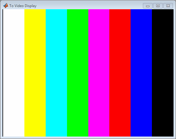
  • Test pattern generator — On-chip TPG. The TPG creates input frames at the requested resolution. The test pattern is a fixed color bar pattern. When you select the TPG, you do not need a camera or other HDMI source connected to the FMC card.

    Video test pattern captured when you set the Video source parameter to Test pattern generator.

Select from HD and SD TV resolutions and common computer frame sizes. If the resolution you select does not match the resolution of the HDMI input source, the block returns an error.

For most frame sizes, this parameter is informational. Frame size 576p supports only 50 fps. Most other frame sizes support only 60 fps, except for 720p and 1080p.

When you use frame sizes 720p or 1080p, you can select from the available frame rates.

The block sets the Simulink sample time for the captured video frames to 1/Frame rate.

Specify the format of the pixel stream as one of these values.

  • RGB — Three 8 bit color components per pixel, which is 24 bits per pixel total. You can also select the color space conversion standard and whether the block returns a multidimensional signal or three separate color signals. For details, see the Use color space conversion specified by and Image signal parameters, respectively.

  • Y only — Grayscale. One 8 bit component per pixel. The block returns the frames on the Y output port.

  • YCbCr 4:2:2 (default) — Also known as YUYV. An 8 bit Y component and an interleaved 8 bit CbCr component. The effective pixel size is 16 bits. The block returns the component frames on the Y, Cb, and Cr output ports.

To capture video from a board with a deployed design that customizes the FPGA user logic, this parameter must match the video format in the deployed design. In the generated software interface model, this parameter displays the configuration you selected in the Video Capture HDMI block before you generated HDL code. When you use the default FPGA logic, you can select any pixel format.

The HDMI input video on the Zynq boards is delivered in YCbCr 4:2:2 format. Your configuration of the Video Capture HDMI block sends control signals to the FPGA. The FPGA logic converts the input and output data according to the pixel format you specify.

Pixel FormatFPGA Logic Action
YCbCr 4:2:2 (YUYV)Passes through.
RGB

Converts HDMI input pixels from YCbCr 4:2:2 to RGB, and converts from RGB to YCbCr 4:2:2 for the HDMI output.

Y only

Uses the Y component of HDMI input pixels in YCbCr 4:2:2, and outputs the Y component of YCbCr 4:2:2 for the HDMI output.

This parameter specifies the equation that is used to convert between RGB and YCbCr color spaces. For more information, see the Color Space Conversion (Computer Vision Toolbox) block.

To capture video from a board with a deployed design that customizes the FPGA user logic, this parameter must match the video format in the deployed design. In the generated software interface model, this parameter displays the configuration you selected in the Video Capture HDMI block before you generated HDL code.

Dependencies

To enable this parameter, set Pixel format to RGB.

Select this parameter to bypass the user logic section of the FPGA and send the input video frames directly to the HDMI output. When you select this option, capture point A and B observe the same video data.

You can import frames into Simulink from the input or output of the user logic section of the FPGA. This section of logic is a pass-through in the default FPGA image. Generate HDL from your Simulink subsystem to insert into the user logic section of the FPGA. The data path diagram in the Description section of this page shows the capture points A and B.

  • Input to FPGA user logic (A) — Capture frames after conversion and before the user logic section.

  • Output from FPGA user logic (B) — Capture frames after the user logic section and before conversion back to HDMI output.

  • No capture — No video data is passed to Simulink. You can still use the block to control the data path and video format on the FPGA.

Specify the RGB output stream format as one of these values.

  • Separate color signals — The block returns separate height-by-width matrices for each color component. In this case, the block has R, G, and B output ports.

  • One multidimensional signal — The block returns a single 3-by-height-by-width matrix. In this case, the block has an Image output port.

Dependencies

To enable this parameter, set Pixel format to RGB.

This parameter is set to Pixel-stream video and is read-only because the default FPGA image uses the Vision HDL Toolbox™ custom streaming interface. The signal protocol for this interface matches that simulated in the Simulink model.

This parameter must match the implementation of the pixel-stream interface of the FPGA image that is running on the board from which you are capturing data. To capture data from a design that uses the AXI4-Stream Video interface, use your generated targeted hardware interface model, where this parameter is set to AXI4-stream video, or copy the Video Capture HDMI block from that model.

If your FPGA image uses the Vision HDL Toolbox interface and you use the Video Capture HDMI block with this parameter set to AXI4-stream video, the model returns this error message.

command "/mnt/visionzynq-tools/visionzynq-target-dev.elf --write --device=/dev/mwipcore_vht2vs --address=0x00 0x01".

Error evaluating 'StartFcn' callback of SubSystem block (mask) 'gm_vzImageRotation_PixelStream_tgthw_interface/Video Capture HDMI/VisionZynq Internal/FrameCapture_Init/Frame Format Check'. 
Callback string is 'visionzynq.internal.vzmask(gcb, 'FrameFormatCheckCb','StartFcn');' 
Caused by: Error executing command "/mnt/visionzynq-tools/visionzynq-target-dev.elf --write --device=/dev/mwipcore_vht2vs --address=0x00 0x01".
If your FPGA image uses the AXI4-Stream interface and you set this parameter to Pixel-stream video, the block does not capture any data to the model.

Tips

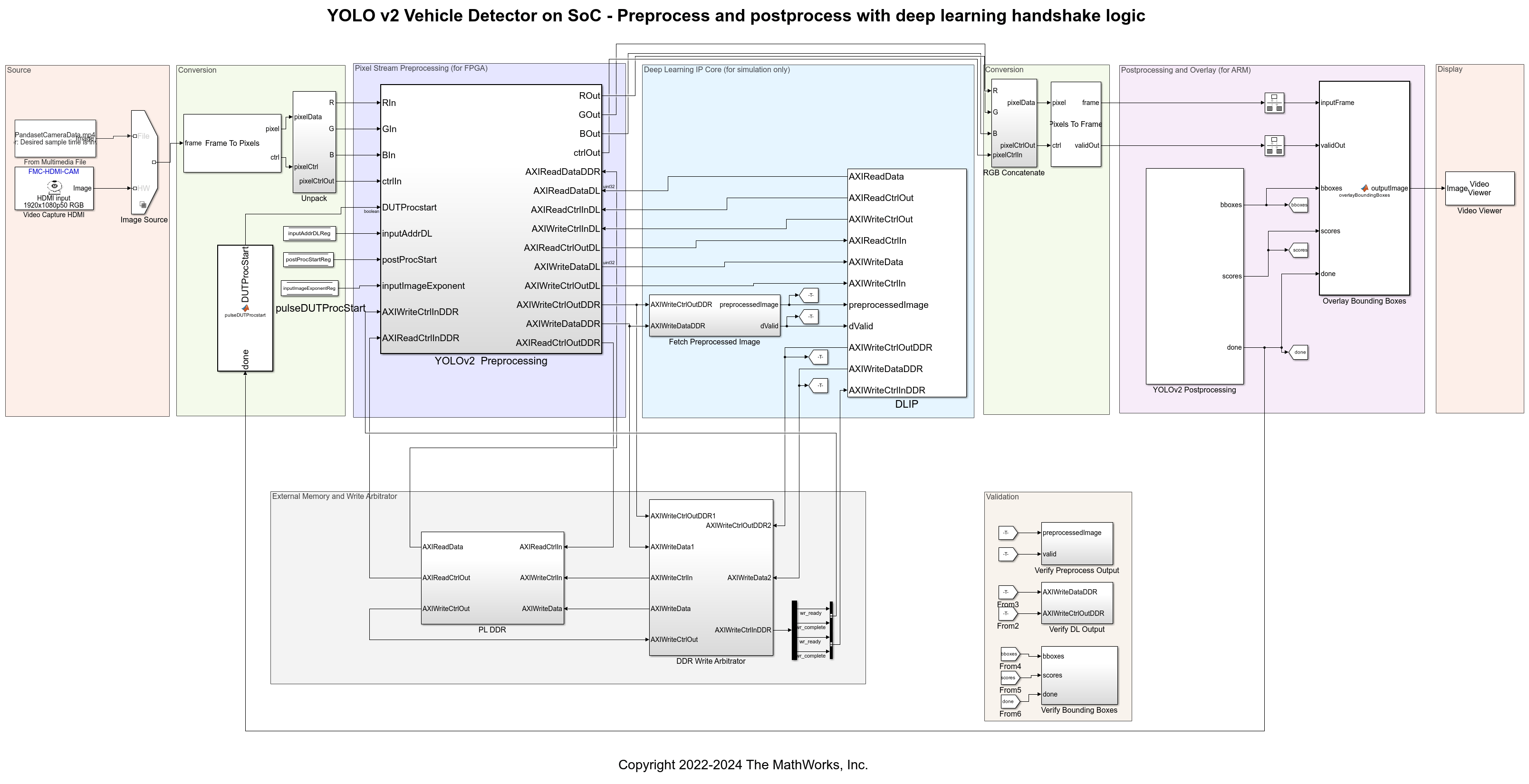
When you use the RGB with DL Processor reference design, you can deploy the design and then open a simple capture model, such as the Getting Started with Vision Zynq Hardware model, to capture video while the design runs on the board. The video captured is the result of the postprocessing operation in the ARM processor. To capture video from this reference design, set the Video Capture HDMI block parameters to these values.

  • Video source must be HDMI input. This reference design does not contain a test pattern generator.

  • Frame size must be 1080p HDTV (1920x1080p).

  • Pixel format must be RGB.

  • The Bypass FPGA user logic and Capture point parameters have no effect with this reference design.

For an example, see YOLO v2 Vehicle Detector with Live Camera Input on Zynq-Based Hardware (Vision HDL Toolbox).

Version History

Introduced in R2023a