Analyzing Impact of Task Overruns in Control System
This example shows how to assess stability and performance of an embedded controller in the presence of task overruns.
Stability and performance design of closed-loop systems typically assume constant execution times. If execution times vary but stay within expected bounds, systems can treat them as variable delays and by using the concept of phase margin. If the delays exceed expected bounds, the stability of the control system cannot be verified using classical linear techniques.
Application Description
The application in this example is a video camera platform that tracks objects of interest. An example of such a system is a flying drone that tracks an object, keeping it in the center of the image. The platform moves along a single axis.
Based on the expected target dynamics, the video feed must have a frame rate of 25 frame per second. To achieve this, the application controller has three loops:
An outer loop for the video tracking and subsequent position control, running at 40 ms.
An intermediate speed loop for inertial stabilization, running at 10 ms.
An inner current loop for controlling the actuator torque, running at 2 ms.
This behavioral model represents the application.
open_system('soc_overrunanalysis_behavioral')
The model simulates the target velocity using the Signal Editor block.
In this example, you model the target velocity using either a trapezoidal waveform or a sine waveform.
Ideal Behavioral Simulation
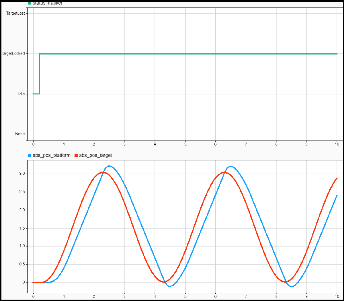
Simulate the model by clicking Run. Verify that the application tracks the moving target. Observe that the abs_pos_platform signal closely follows the abs_pos_target_analog signal. This result is expected as the model contains the controller that is well-tuned and variable task execution times and task overruns are not simulated.
Behavioral Simulation with Execution Time Modeling
This model is an extended version of the behavioral model that includes task execution timing in the processor running the control algorithm.
open_system('soc_overrunanalysis_taskmanager')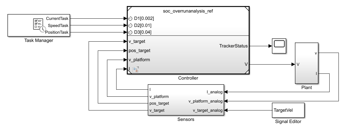
Enter task execution timing information in the Task Manager block. The accuracy of the simulation depends on the accuracy of the task execution times.
This table shows task execution times, which follow a normal distribution. Typically, you identify these execution times by measuring algorithm speed on hardware.
                  %        min      mean        max        std
CurrentTask     100   0.000060  0.000080   0.000120   0.000300
SpeedTask       100   0.000060  0.000080   0.000120   0.000300
PositionTask     95   0.004000  0.005000   0.007000   0.000300
                  5   0.040000  0.050000   0.070000   0.000300
Best-Case Execution Times
Click the Task Manager block and set task execution times corresponding to their minimum values. Simulate the model and inspect the value of the status_tracker signal in the Simulation Data Inspector.

The target remains locked once the model acquires it, and the abs_pos_platform signal closely follows the abs_pos_target signal. Because the model contains a well-tuned-controller and encounters no task overruns occur, these results are consistent with the behavior of the ideal system.
Worst-Case Execution Times
Click the Task Manager block and set task execution times corresponding to their minimum values. Simulate the model and inspect the value of the status_tracker signal in the Simulation Data Inspector. The target remains locked for a short time after it is acquired but the model loses it several times and cannot lock it again. The abs_pos_platform and abs_pos_target signals start with a significant initial discrepancy before diverging completely from one another.
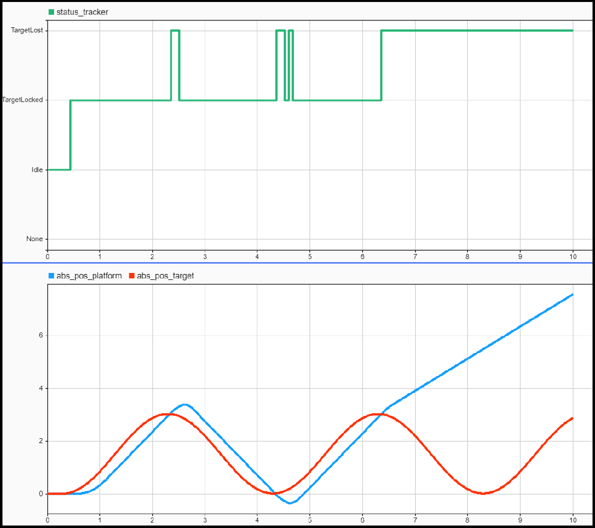
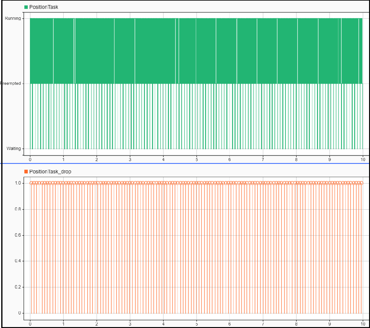
To understand the reason for the behavior of the system behavior, analyze the task execution plots in the Simulation Data Inspector. Every instance of the PositionTask overruns and the next task instance drops. The PositionTask runs every 80 ms, which leads to the large signal discrepancy. Corrective measures that you can apply include:
Adjusting the period of the PositionTask and retune the position control loop algorithm accordingly.
Reducing the execution time of the position control loop algorithm by using a faster processor.
Random Execution Times
Set the distribution of execution times by using the Task Manager block. In this example, the default distributions for CurrentTask and SpeedTask are normal distributions, and the default distribution for Position task is a multimodal distribution.
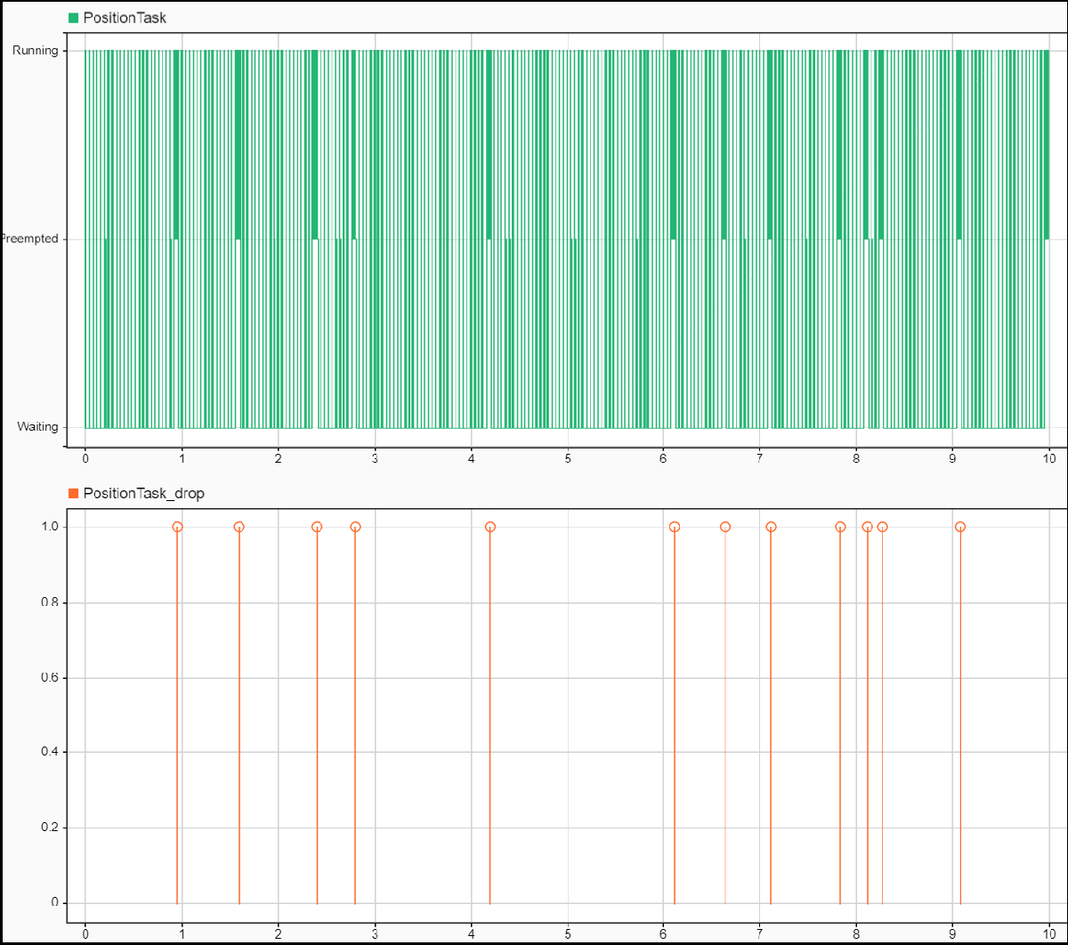
Simulate the model and inspect the value of the status-tracker signal. The target remains locked for most of the simulation but the model temporarily loses it twice. The abs_pos_platform signal follows the abs_pos_target signal but has larger differences than in the Best Execution Time section. This behavior occurs because the controller sporadically receives the sensor data with too large a delay due to task overruns.

To understand this, analyze the task execution graphs. The PositionTask sporadically overruns and drops the next task instance. However, behavior is less frequent than in the Worst-Case Execution Times section. The model follows the target more consistently, though not to the standard required by application. Corrective measures that you can apply include:
Avoid sporadic task overruns by using a more efficient implementation of the position control loop algorithm.
Identifying and eliminating the system disturbances or inefficiencies causing sporadic task overruns.
Large-Scale Sensitivity Analysis
Accounting for combinations of operating conditions requires large-scale sensitivity analysis of the controller. This model includes modifications that use Simulink Test software.
open_system('soc_overrunanalysis_simulinktest')
You can change the duration of PositionTask during simulation by using the input port of the Task Manager block. A Random Number block generates duration value. Simulink Test controls the mean and variance parameters. A Test Sequence (Simulink Test) block replaces the Scope block from the model in the Behavioral Simulation with Execution Time Modeling section.
In Simulink, click the Apps tab and select Simulink Test. In the Test tab, click Simulink Test Manager (Simulink Test) and open the soc_overrunanalysis_simulinktest_cases test file.
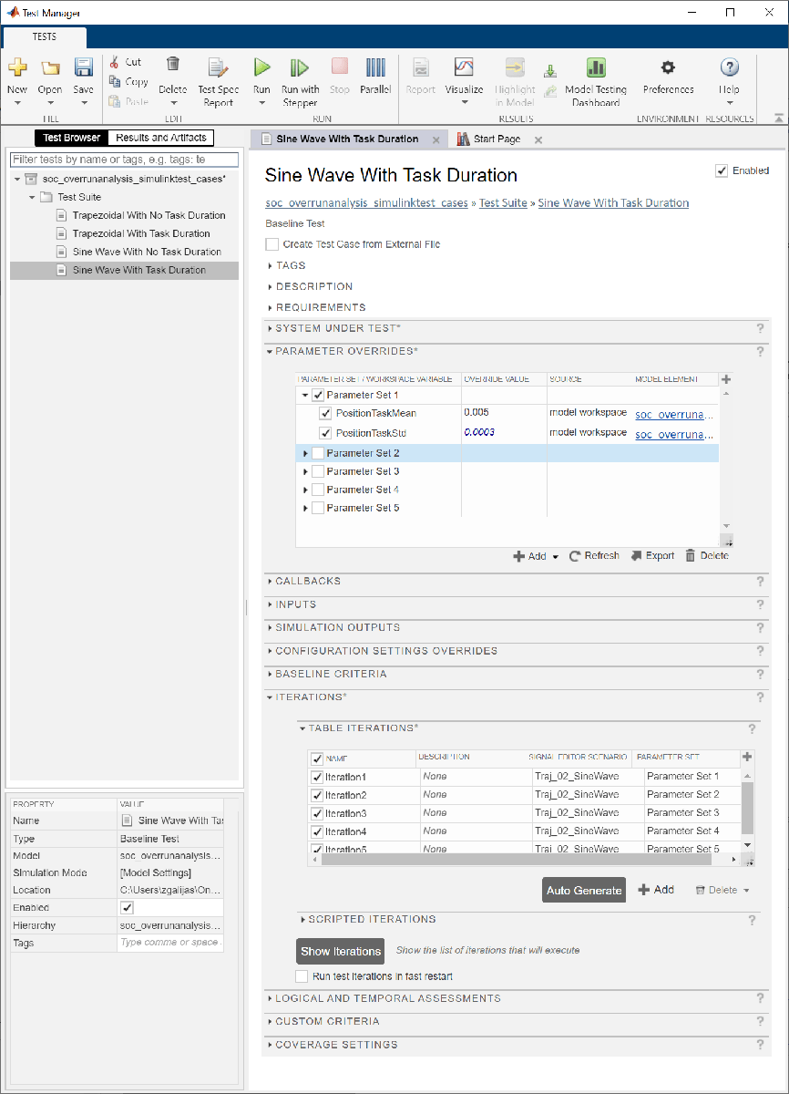
The test suite includes these tests:
Trapezoidal trajectory with no task duration
Trapezoidal trajectory with task duration
Sine wave trajectory with no task duration
Sine wave trajectory with task duration
Tests with task duration simulation vary the PositionTask duration by setting the parameters of the Random Generator block to one of the five defined parameter sets. In the Simulink Test Manager (Simulink Test), click Run for each of the four tests. If you have a Parallel Computing Toolbox license, you can enable parallel test execution by clicking Parallel before pressing Run.
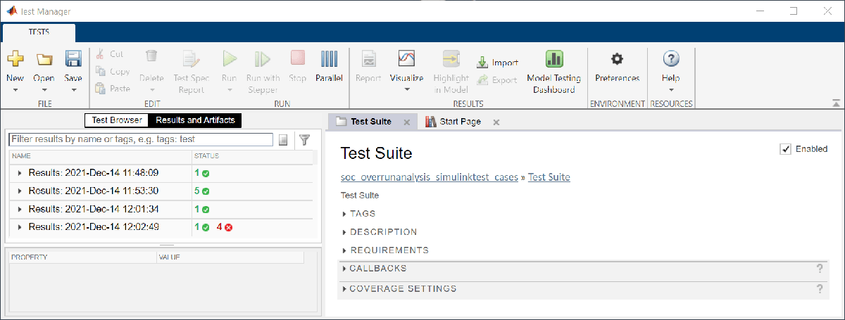
After the test suite completes, analyze the results by clicking on the Results And Artifacts tab. Out of the twelve tests, eight passed and four failed. Expand the results of the failed tests, review the recorded signals, and determine the cause of each test failure. The test failure conditions define the practical stability bounds of the control system and can help direct potential design improvements to the control algorithm and system.
Further Exploration
Extend the target dynamics, platform dynamics, and controller design to support higher degrees of freedom, such as two-dimensional or three-dimensional tracking.
Improve the granularity of the control system stability bounds by expanding the set of test cases.