Channel I/O
The RF chip of your radio hardware determines the number of channels you can use for sending and receiving data.
| Radio Hardware | RF Chip | Number of Channels | Supported RF Ports |
|---|---|---|---|
ZC706 and FMCOMMS5 | 2 x AD9361 | 4 | For AD9361 Chip A: TX1A_A, RX1A_A, TX2A_A, RX2A_A For AD9361 Chip B: TX1A_B, RX1A_B, TX2A_B, RX2A_B |
ADI RF SOM ZC706 and FMCOMMS2 or FMCOMMS3 ZedBoard™ and FMCOMMS2 or FMCOMMS3 ZCU102 and FMCOMMS2 or FMCOMMS3 | AD9361 | 2 | TX1A, RX1A, TX2A, RX2A |
ZC706 and FMCOMMS4 ZedBoard and FMCOMMS4 ZCU102 and FMCOMMS4 | AD9364 | 1 | TXA, RXA |
Channel I/O Using AD9361 or AD9364
With an AD9361-based radio hardware, you can send or receive data
using a single channel or you can use both channels. With an AD9364-based radio
hardware, you can send or receive data using only a single channel. For sending data,
use the comm.SDRTxAD936x
System object™ or the AD936x
Transmitter block. For receiving data, use the comm.SDRRxAD936x
System object or AD936x Receiver
block.
Transmit Data on Single Channel Using System Object
Create a transmitter System object for the AD9361-based or AD9364-based radio hardware.
tx = sdrtx('AD936x', ...
           'IPAddress','192.168.3.2', ...
           'CenterFrequency',2.4e9, ...
           'BasebandSampleRate',1e6);
Set channel mapping to
1to specify single channel use on channel 1. Alternatively, for the AD9361-based radio hardware, you can also specify single channel use on channel 2 by setting the channel mapping to2.tx.ChannelMapping = 1;
Create a DPSK modulator System object to modulate the transmitted signals.
mod = comm.DPSKModulator('BitInput',true);Transmit data. Because only one channel is in use, the number of columns in
modSignalis also1.for counter = 1:20 data = randi([0 1],30,1); modSignal = mod(data); tx(modSignal); end
Release the System object.
release(tx);
Transmit Data on Single Channel Using Simulink Block
This model is set up to transmit data on a single channel. Set the Enable Channel 1 option of the AD936x Transmitter block. The underflow port is disabled by clearing the Enable output port for underflow indicator parameter. The Sine Wave block is configured to generate a 1 kHz sine wave, sampled at 1 MHz. When you run this model, the AD936x Transmitter block sends the generated sine wave through the air. You can inspect the generated data in the Spectrum Analyzer.
![]()
Receive Data on Single Channel Using System Object
Create a receiver System object for the AD9361-based or AD9364-based radio hardware.
rx = sdrrx('AD936x');Set the channel mapping to indicate that only channel 1 is in use.
rx.ChannelMapping = 1;
Receive data. Because only one channel is in use, the number of columns returned in
datais also1.[data,validData,overflow] = rx();
Release the System object.
release(rx);
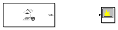
Receive Data on Single Channel Using Simulink Block
This model is set up to receive data on a single channel. Set the Enable Channel 1 option of the AD936x Receiver block. The overflow port is disabled by clearing the Enable output port for overflow indicator parameter. The output data type is set to double. When you run this model, the connected Spectrum Analyzer displays the data noise received through the air. To generate an output tone, explore the Loopback parameter options on the Advanced tab. To generate a sine wave, set the Test signal injection parameter to Tone Inject Rx and the Signal generator mode to Tone.
Transmit Data on Multiple Channels Using System Object
Create a transmitter System object for the AD9361-based radio hardware.
tx = sdrtx('AD936x', ...
           'IPAddress','192.168.3.2', ...
           'CenterFrequency',2.4e9, ...
           'BasebandSampleRate',1e6);
Set the channel mapping to
[1 2]to indicate that both channels are in use.tx.ChannelMapping = [1 2];
Create a DPSK modulator System object to modulate the transmitted signals.
mod = comm.DPSKModulator('BitInput',true);Transmit data. Because two channels are in use, duplicate
modSignalto form a two-column vector.for i = 1:5 data = randi([0 1],30,1); modSignal = mod(data); tx([modSignal modSignal]); end
Release the System object.
release(tx);
Transmit Data on Multiple Channels Using Simulink Block
This model is set up to transmit data on two channels. To transmit data on multiple channels, select Enable Channel 1 and Enable Channel 2 in the AD936x Data Write block mask. Deselect the Enable output port for underflow indicator parameter. The Sine Wave Channel 1 block is configured to generate a 1 kHz sine wave. The Sine Wave Channel 2 block is configured to generate an 8 kHz sine wave. Both sine waves are sampled at 1 MHz. When you run this model, the AD936x Data Write block sends the generated and combined sine waves through the air. You can inspect the generated data in the Spectrum Analyzer blocks.
Model 'Transmit_Data_on_Multiple_Channels_Using_Simulink_Block' was exported from R2025a to R2024b. To find blocks that were removed during the export operation, <a href="matlab:slexportprevious.utils.displayReplacedBlocks('Transmit_Data_on_Multiple_Channels_Using_Simulink_Block')">click here</a>. Save the model to remove this notification.
![]()
Receive Data on Multiple Channels Using System Object
Create a receiver System object for the AD9361-based radio hardware.
rx = sdrrx('AD936x');Set channel mapping to
[1 2]to indicate the number of channels in use.rx.ChannelMapping = [1 2];
Receive data. Because multiple channels are being used, the number of columns returned in
datais also 2.[data,validData,overflow] = rx();
Release the System object.
release(rx);
Receive Data on Multiple Channels Using Simulink Block
This model is set up to receive data on two channels. To receive on multiple channels, select the Enable Channel 1 and Enable Channel 2 in the AD936x Data Read block mask. Deselect the Enable output port for overflow indicator parameter. The output data type is set to double. When you run this model, the connected Spectrum Analyzer blocks display the data noise received from the air through each channel. To generate an output tone, explore the Loopback parameter options on the Advanced tab. To generate a sine wave, set the Test signal injection parameter to Tone Inject Rx and the Signal generator mode to Tone. These settings apply to both channels.
Model 'Receive_Data_on_Multiple_Channels_Using_Simulink_Block' was exported from R2025a to R2024b. To find blocks that were removed during the export operation, <a href="matlab:slexportprevious.utils.displayReplacedBlocks('Receive_Data_on_Multiple_Channels_Using_Simulink_Block')">click here</a>. Save the model to remove this notification.

Channel I/O Using FMCOMMS5
With an FMCOMMS5 Zynq® radio hardware, you can send or receive data using a single channel or you
can use multiple channels. For sending data, use the comm.SDRTxFMCOMMS5
System object or the FMCOMMS5
Transmitter block. For receiving data, use the comm.SDRRxFMCOMMS5
System object or the FMCOMMS5
Receiver block. You can specify the number of channels in use with the
Channel mapping parameter for blocks and with the
ChannelMapping property for System objects. Specify the number
of channels as one of the following options:
Integer from 1 to 4 — The integer value indicates which single channel is in use.
[N
                        M]
, where N and M are distinct integers from 1 to 4 — Channels N and M are in use.[1 2 3 4]— All four channels are in use.
The RF chip of the radio hardware determines the number of channels you can use for sending or receiving data. For the FMCOMMS5, two AD9361 RF chips are used to provide support for four channels. The channels specified by 1 and 2 are situated on the first AD9361 chip. The channels specified by 3 and 4 are situated on the second AD9361 chip. Using multiple channels across the two chips has certain limitations. For more information, see Multiple Channel Synchronization for FMCOMMS5.
The following examples show how to send and receive data on four channels with an FMCOMMS5 radio hardware using System objects. The steps for sending and receiving data with an FMCOMMS5 radio hardware on a single channel or two channels are similar to the steps outlined for the AD9361 radio hardware in .
Transmit Data on Four Channels Using System Object
Create a transmitter System object for the FMCOMMS5 radio hardware.
tx = sdrtx('FMCOMMS5', ...
           'IPAddress','192.168.3.2', ...
           'CenterFrequency',2.4e9, ...
           'BasebandSampleRate',1e6);
Set the channel mapping to
[1 2 3 4]to indicate that all four channels are in use.tx.ChannelMapping = [1 2 3 4];
Create a DPSK modulator System object to modulate the transmitted signals.
mod = comm.DPSKModulator('BitInput',true);Transmit data. Because four channels are in use, create a four-column vector using
modSignal.for i = 1:5 data = randi([0 1],30,1); modSignal = mod(data); tx([modSignal modSignal modSignal modSignal]); end
Release the System object.
release(tx);
Receive Data on Four Channels Using System Object
Create a receiver System object for the FMCOMMS5 radio hardware.
rx = sdrrx('FMCOMMS5');Set channel mapping to
[1 2 3 4]to indicate that all four channels are in use.rx.ChannelMapping = [1 2 3 4];
Receive data. Because multiple channels are being used, the number of columns returned in
datais 4.[data,validData,overflow] = rx();
Release the System object.
release(rx);