Set Up AMD FPGA and SoC Devices
R2026bTo connect a supported Intel hardware board to MATLAB® or Simulink®, you must set up the board by using the Hardware Setup tool. The tool guides you through the process of registering, configuring, and connecting your hardware board.
Open the Hardware Setup tool
Launch the Hardware Setup tool by using the Add-Ons panel, the hdlHardwareSetup (HDL Coder) function, or the HDL Coder™ app in Simulink.
Using Add-Ons Panel
To open the Hardware Setup tool from the Add-Ons panel, in MATLAB, select Add-Ons > Manage Add-Ons.
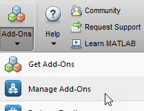
To launch the Hardware Setup tool, in the Add-Ons panel, point to required support
package and click the Settings button,  .
.
Using hdlHardwareSetup Function
Start the Hardware Setup tool by using hdlHardwareSetup (HDL Coder) function. To open the Hardware Setup tool
programmatically, enter this command in the MATLAB Command Window:
hdlHardwareSetup
Using HDL Coder App
To open the Hardware Setup tool from the Simulink Toolstrip:
In the Simulink model, click Apps tab, then select HDL Coder.
On the Simulink Toolstrip, select the HDL Code tab. In the Output section, set the drop-down button to IP Core.
Open the HDL Code Generation > Target tab of Configuration Parameters dialog box by clicking the Settings button on the HDL Code tab. Select the required Target Platform. Click Ok.
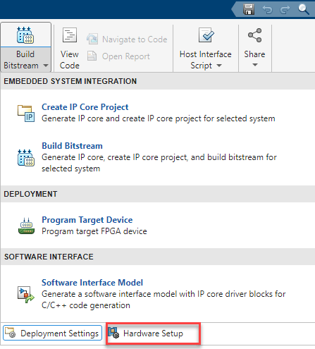
In the HDL Code tab, click Build Bitstream and select Hardware Setup.
Using System on Chip App
Start the Hardware Setup tool by using the System on Chip app in Simulink. To open the Hardware Setup tool from the Simulink toolstrip,
In the Simulink model, click Apps tab and select System on Chip app.
Simulink Toolstrip: On the System on Chip tab, click
Setup Hardwarein Hardware Board.
Hardware Setup Steps
You can use the Hardware Setup tool to configure your target hardware board. The hardware setup involves following steps:
Select Hardware Board and Interface: Select the target hardware board and interfaces and configure the board for HDL IP core generation, deep learning, FPGA verification and debug, or SoC modeling and generation.
Download and Install Third-Party Tools: Download and install the required third‑party tools to configure your board.
Configure Network Card and Write Firmware: Configure the development computer to communicate with the hardware board and write the firmware image to the SD card.
Set Jumper Switches and Connect Hardware: Configure the jumper switches on the hardware board for peripheral mode and connect the board to the development computer.
Verify Configuration and Open Examples: Verify the connection between the development computer and hardware board by using a selected interface. After completing hardware setup, you can choose to open example models.

