5G NR Downlink Signal Measurements Using AMD RFSoC Device
This example shows how to perform EVM measurements and SSB signal quality measurements for 5G downlink signals with a practical receiver using SoC Blockset™ to target a AMD® Zynq® UltraScale+(TM) RFSoC ZCU111 evaluation board.
This example presents a practical setup to characterize the performance of a 5G NR Receiver design deployed to an RFSoC device. The SoC implementation from the 5G NR SIB1 Recovery for FR1 and FR2 Using AMD RFSoC Device example is used. The design supports flexible operations that can be controlled externally through its AXI interface, allowing it to be reused for multiple purposes. The setup consists of the SoC implementation developed in Simulink® and deployed to the target device, and MATLAB® control and measurement algorithms running on the host. The operations performed by each component are described. The setup is then used to measure the performance for two use cases, firstly to verify the performance of the receiver, and secondly to characterize the RFSoC data converter front-end.
Supported Hardware Platforms
This example supports the AMD Zynq UltraScale+ RFSoC ZCU111 evaluation kit + XM500 Balun card.
Measurement Setup
The diagram shows the setup used in this example. The SoC implementation of the NR Receiver is deployed to the RFSoC, and MATLAB controls and monitors the design. Data from the FPGA design is post-processed in MATLAB to perform the downlink signal measurements.

The runNRDownlinkSignalMeasurementsHardware script runs the characterization test:
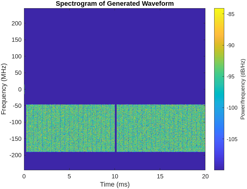
Generate a 5G waveform with 5G Toolbox®.
Load the waveform onto the RFSoC.
Configure the transmit repeat and data capture operations.
Run cell search, MIB recovery, and wideband grid recovery.
Read cell search and MIB recovery results from the board.
Perform SSB signal quality measurements.
Read the wideband resource grid from the board.
Calculate EVM measurements.
The operation and implementation of the transmit repeat and data capture stages are described. For more information on the 5G NR Receiver design and the EVM and SSB signal quality measurements see the NR HDL Downlink Signal Measurements (Wireless HDL Toolbox) example.
Transmit Repeat
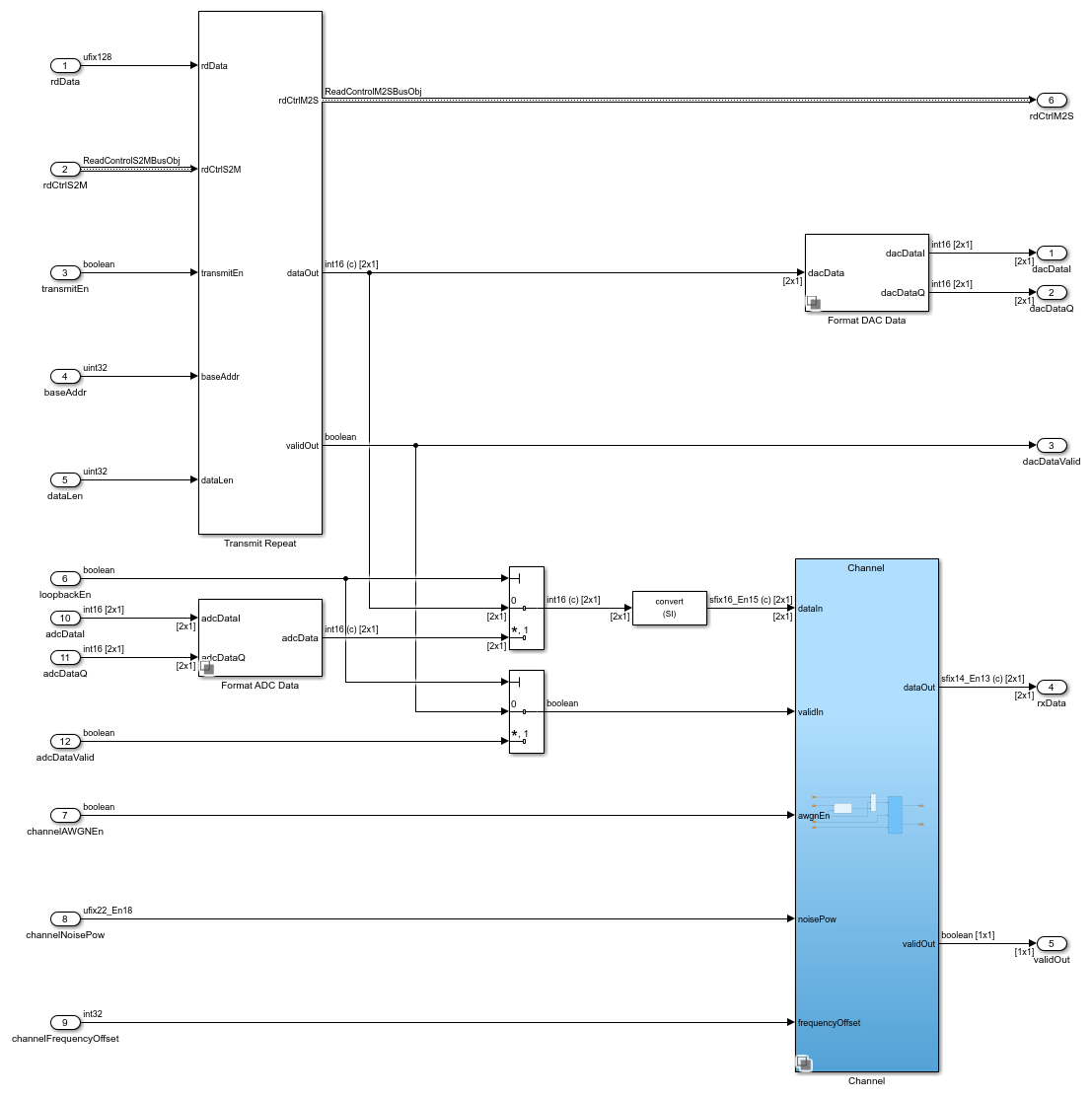
To perform EVM measurements the transmitted and received resource grids are compared. Therefore, the input to the receiver must contain known data configuration and content. 5G Toolbox is used to generate the test waveform, and the contents of the data transmission are retained as the ground truth reference. The transmitted waveform is loaded to external memory before starting the transmission. The soc_nrhdlSIB1Recovery_fpga model implements transmit repeat functionality to drive the receiver with data. The Transmit Repeat subsystem reads a pre-generated waveform from external memory and transmits it repeatedly.
The Radio Interface subsystem which implements the transmit repeat functionality is shown. The transmitted waveform can be connected directly to the DUT with digital loopback, or via external loopback by using the an external cable and the ADC data as input. Digital loopback and external loopback allow the distortion of the 5G Receiver and RFSoC RF data converters to be characterized respectively.
Data Capture To External Memory
To record the wideband OFDM resource grid it is necessary to store large amounts of data at up to a bandwidth of almost 1.5 GiBps. To meet the bandwidth and buffer size requirements the RFSoC PL DDR, which is connected directly to the FPGA, is used. The Data Capture subsystem converts the data and valid input stream protocol to the AXI manager protocol for external memory random access writes. The subsystem is controlled by specifying the capture source, length and offset.
Use the
captureSourceport to choose between multiple signals to capture, only one signal can be captured at a time.Use the
captureLenport to specify the number of samples in the data capture.Use the
offsetport to delay the data capture by a number of samples.

Build and Deploy
The nrsocexamples namespace contains two utility functions to build and deploy the SoC image for the soc_nrhdlSIB1Recovery_top model. These functions use the socModelBuilder object to automate the build and deploy steps.
1. Build the 5G Receiver SoC image for the ZCU111.
nrsocexamples.buildSoCImage("soc_nrhdlSIB1Recovery_top","FPGA only")2. Deploy the SoC image to the ZCU111. This will automatically deploy to the previous AMD board connection.
nrsocexamples.deploySoCImage("FPGA only")Receiver Characterization with Digital Loopback
To validate the measurement setup a controlled scenario with digital loopback is used. The known input to the receiver means results can be compared to the those obtained through simulation with the same set of inputs. The digital loopback setup accelerates the process of characterizing the receiver because tests run on the board are several orders of magnitude faster than an equivalent simulation. You can examine the performance of the receiver in different scenarios by applying known distortions to the input waveform. This example shows the result of running the measurement setup with a distortionless waveform. The measurement results show the minimal distortion introduced by the receiver and quantization.
Run the downlink signal measurements with digital loopback.
runNRDownlinkSignalMeasurementsHardware
  Generating test waveform
  Writing test waveform to DDR
Searching for PSS at: 0 kHz
Hardware PSS Search:
      NCellID2    timingOffset    pssCorrelation    pssEnergy    frequencyOffset
      ________    ____________    ______________    _________    _______________
0 2224 1.279 1.2856 10
  Cell ID: 249
  Hardware PSS Demod:
      NCellID2    timingOffset    pssCorrelation    pssEnergy    frequencyOffset
      ________    ____________    ______________    _________    _______________
0 2224 1.279 1.2856 10
SSB measurements:
      Measurement    Hardware
      ___________    ________
"RSRP" 10.084
"RSSI" 33.257
"RSRQ" -10.162
"SINR" 52.496Reading captured OFDM grid data
Performing EVM measurements
  Transmitted PDSCH exceeds the number of OFDM symbols in the demodulated resource grid.
   Extracting OFDM symbols up to 1120 contained in the transmitted grid.
   Increase the length of the demodulated resource grid to compare more data.
Baseline EVM RMS: 0.030145%


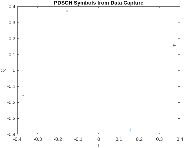
RF Data Converter Characterization with External Loopback
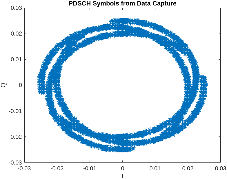
The measurement setup can also be used to characterize the performance of the radio front-end on the target board. The RF data converters implement many complex processing stages that can apply distortion to the received waveform. Evaluating the performance of the receiver under these impairments is an important step in validating the design. This example show one result of running the measurement setup in external loopback mode. The exact results will vary based on external factors affecting the RF electronics performance. These results show that the SSB signal quality is still high. However, the Baseline EVM of the grid is poor, indicating a large impairment. The PDSCH Symbols from Data Capture figure shows that the impairment is due to phase spreading of the constellation symbols. This is caused by a linear phase offset across each subcarrier introduced by a timing estimate error in the OFDM demodulation.
Change the loopbackEn variable to '1' in the Test bench options section of the script. This configures the radio interface to output the transmit repeat data through the RFDC DAC and connect the ADC to the receiver input. To perform external loopback on the hardware you must connect a cable between J7 and J2 on the XM500 balun card, with a 3000-4300 MHz bandpass filter in-line.
Run the downlink signal measurements with external loopback.
runNRDownlinkSignalMeasurementsHardware
  Generating test waveform
  Writing test waveform to DDR
Searching for PSS at: 0 kHz
Hardware PSS Search:
      NCellID2    timingOffset    pssCorrelation    pssEnergy    frequencyOffset
      ________    ____________    ______________    _________    _______________
0 9.67e+05 0.0051171 0.0053305 85
  Cell ID: 249
  Hardware PSS Demod:
      NCellID2    timingOffset    pssCorrelation    pssEnergy    frequencyOffset
      ________    ____________    ______________    _________    _______________
0 9.67e+05 0.0051171 0.0053604 85
SSB measurements:
      Measurement    Hardware
      ___________    ________
"RSRP" -13.867
"RSSI" 9.4331
"RSRQ" -10.29
"SINR" 39.412Reading captured OFDM grid data
Performing EVM measurements
  Transmitted PDSCH exceeds the number of OFDM symbols in the demodulated resource grid.
   Extracting OFDM symbols up to 1120 contained in the transmitted grid.
   Increase the length of the demodulated resource grid to compare more data.
Baseline EVM RMS: 98.8401%
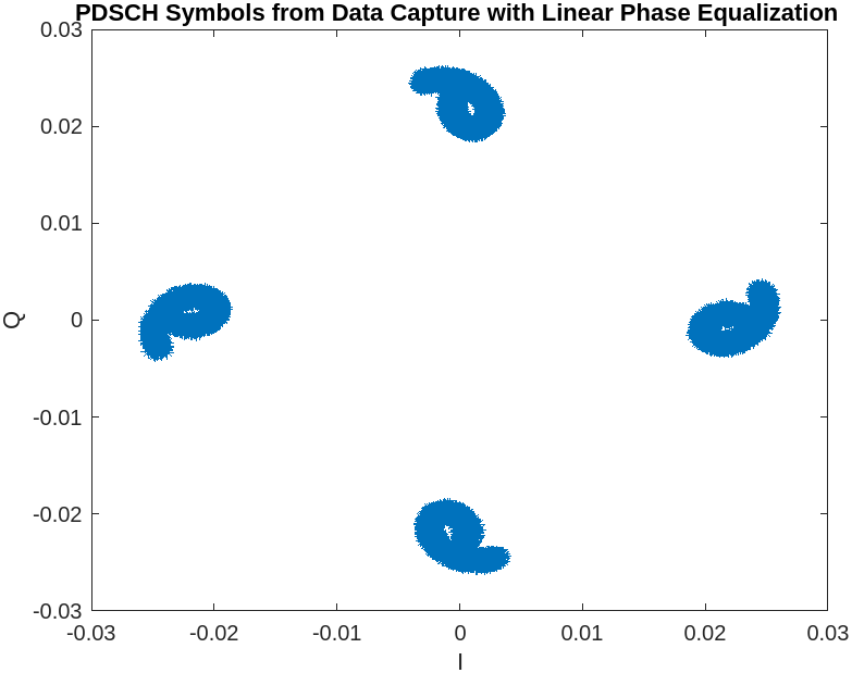
Linear Phase Equalization
The linear phase offset is estimated by measuring the phase error between each the recevied and expected value of each subcarrier in the first OFDM symbol. A line of best fit is then used to model the phase error by plotting the phase error against the subcarrier number. The estimate is then used to correct the phase error across every OFDM symbol. The PDSCH Symbols from Data Capture with Linear Phase Equalization figure shows the constellation after the phase error is corrected, allowing the distortion introduced by the RF data converters to be seen. The Baseline EVM measurement post linear phase equalization is significantly improved.
Baseline EVM RMS with linear phase equalization: 10.2112%
File Structure
This example uses these files.
Simulink models
soc_nrhdlSIB1Recovery_top.slx: This Simulink model represents the full hardware/software co-design SoC implementation. This model references thesoc_nrhdlSIB1Recovery_fpgaandsoc_nrhdlSIB1Recovery_procmodels to implement the FPGA and Processor logic respectively.soc_nrhdlSIB1Recovery_fpga.slx: This Simulink model represents the portion of the hardware/software co-design deployed to the FPGA. The model integrates the NR 5G receiver design with the hardware interfaces and logic required to operate on an SoC. This model references thenrhdlDDCCore,nrhdlSSBDetectionCore,nrhdlSSBDecodingCore,nrhdlPolarDecodingChainCore,nrhdlGridDemodulationCore,nrhdlCORESET0DecodingCore, andnrhdlLDPCDecodingChainCoremodels.soc_nrhdlSIB1Recovery_proc.slx: This Simulink model represents the portion of the hardware/software co-design deployed to the Processor. The model only supports SIB1 Recovery operations and is not used for performing downlink signal measurements.soc_nrhdlSIB1Recovery_hostUDPReceive.slx: This Simulink model runs on the host machine and logs results from the SoC processor sent over UDP.nrhdlDDCCore.slx: This model implements a DDC to create sample streams for SIB1 and SSBs.nrhdlSSBDetectionCore.slx: This model implements the SSB detection algorithm.nrhdlSSBDecodingCore.slx: This model implements the SSB decoding algorithm.nrhdlPolarDecodingChainCore.slx: This model implements the common polar decoding chain.nrhdlGridDemodulationCore.slx: This model implements the grid demodulation algorithm.nrhdlCORESET0DecodingCore.slx: This model implements the CORESET0 decoding algorithm.nrhdlLDPCDecodingChainCore.slx: This model implements the SIB1 LDPC decoding algorithm.
Simulink data dictionary
nrhdlReceiverData.sldd: This Simulink data dictionary contains bus objects that define the buses contained in the example models, and design constants for the SoC implementation.
MATLAB code
setupNRSIB1RecoveryTopModel.m: This script defines the workspace variables required to setup thesoc_nrhdlSIB1Recovery_topmodel for code generation and simulation.runNRDownlinkSignalMeasurementsHardware.m: This script runs the deployed 5G NR Receiver design on the board to perform wideband grid recovery, and then performs EVM and SSB signal quality measurements on the data returned to MATLAB.nrhdlexamples: Namespace containing the MATLAB reference code and utility functions for verifying the implementation models.nrsocexamples: Namespace containing utility functions for running the SoC implementation on the target.
See Also
Topics
- NR HDL Downlink Signal Measurements (Wireless HDL Toolbox)