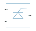
Average-Value Inverter (Three-Phase)
Average-value DC Voltage to three-phase AC voltage converter with fixed power loss
Libraries:
Simscape /
Electrical /
Semiconductors & Converters /
Converters
Description
The Average-Value Inverter (Three-Phase) block models an average-value, full-wave inverter. It converts DC voltage to three-phase AC voltages and converts three-phase AC power demand to DC power demand. The corresponding DC power demand is equal to the sum of the fixed power loss and the AC power demand.
You can use the Average-Value Inverter (Three-Phase) block only as a full-wave inverter. It behaves as a DC-voltage-controlled AC voltage source. The ratio you specify determines the ratio between the DC voltage and the AC voltage.
The figure shows the equivalent circuit for the inverter as a full-wave inverter. The Average-Value Inverter (Three-Phase) block does not yield the harmonics that are typically associated with the detailed representation, however, because it performs an average-value power conversion.

Electrical Defining Equations
The voltages are defined by
and
where:
vp and vn are the voltages at the positive and negative terminals of the inverter.
vDC is the voltage difference between the positive and negative terminals of the inverter.
vref is the DC offset.
Vratio is the ratio of rated AC voltage to rated DC voltage for the inverter. See the Ratio of rated AC voltage to rated DC voltage parameter in Parameters for the Vratio values for common inverter control modes.
VRMS is the RMS AC line-line voltage.
V0 is the peak phase voltage.
f is the frequency.
t is the time.
φ is the phase shift.
va, vb, vc are the respective AC phase voltages.
The power, resistance, and currents are defined by
and
where:
ia, ib, and ic are the respective AC phase currents flowing into the inverter.
PAC is the power output on the AC side. PAC has a minimum limit of
0W.Pfixed is the fixed power loss that you specify on the block.
RDC is the resistance on the DC side.
i is the current flowing from the positive to the negative terminals of the inverter.
The inverter starts to create an AC voltage, that is turns on, when the DC supply voltage is above the value that you specify for DC voltage for turn on parameter. It stops inverting, that is turns off, when the DC supply voltage falls below the value that you specify for DC voltage for turn off parameter. When the inverter turns off, the block sets the output AC current to zero.
Ports
Conserving
Parameters
References
[1] Rashid, M. H. Pulse-Width-Modulation Inverters. Upper Saddle River, NJ: Prentice-Hall, 2004, pp. 237–248.
[2] Krause, P. C., O. Wasynczuk, and S. D. Sudhoff. Analysis of Electric Machinery and Drive Systems. Piscataway, NJ: IEEE Press, 2002.
[3] Chung, D. W., J. S. Kim, and S. K. Kul. “Unified voltage modulation technique for real-time three-phase power conversion.” IEEE Transactions on Industry Applications. Vol. 34, no. 2, 1998, pp. 374–380.
[4] Hava, A. M., R. J. Kerkman, and T. A. Lipo. “Simple analytical and graphical methods for carrier-based PWM-VSI drives.” IEEE Transactions on Power Electronics. Vol. 14, 1999, no. 1, pp. 49–61.
