Average-Value Chopper
Average-value chopper
Libraries:
Simscape /
Electrical /
Semiconductors & Converters /
Converters
Description
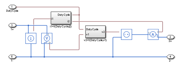
The Average-Value Chopper block represents a controlled average-value chopper. Use the duty cycle input to convert the electrical energy between the two sides. The figure shows the equivalent circuit for the block.

Equations
The input current and output voltage depend on the chopper class that you specify.
Voltage and Current Equations
| Chopper Class | Quadrants | Output Voltage, | Input Current, | ||||
|---|---|---|---|---|---|---|---|
| A | 1st | ||||||
| B | 2nd | ||||||
| C | 1st and 2nd | ||||||
| D | 1st and 4th | ||||||
| E | Four | ||||||
Limitations and Assumptions
Input voltage, v1 is positive.
Power losses are neglected.
The Average-Value Chopper block represents an ideal implementation of a controlled average-value chopper with no dynamics, and it is suitable for low fidelity simulations. For higher fidelity models, use the One-Quadrant Chopper, Two-Quadrant Chopper, or Four-Quadrant Chopper blocks.
Examples
Ports
Conserving
Parameters
References
[1] Trzynadlowski, A. M. Introduction to Modern Power Electronics. 2nd Ed. Hoboken, NJ: John Wiley & Sons Inc., 2010.
Extended Capabilities
Version History
Introduced in R2018b

