PMSM Current Reference Generator
Permanent magnet synchronous machine current reference generator

Libraries:
Simscape /
Electrical /
Control /
PMSM Control
Description
The PMSM Current Reference Generator block implements a current reference generator for permanent magnet synchronous machine (PMSM) current control in the rotor d-q reference frame.
You typically use this block in a series of blocks making up a control structure.
You can generate a voltage reference in the d-q frame by placing this block before a PMSM Current Controller or PMSM Current Controller with Pre-Control block.
You can implement velocity control by placing this block after a Velocity Controller block.
For an example of a full control structure, from machine measurements to machine inputs, see the PMSM Field-Oriented Control block.
Equations
The PMSM Current Reference Generator block obtains the current reference by using one of these methods:
Zero d-axis control (ZDAC)
User-defined lookup tables
Automatically-generated lookup tables
For the ZDAC method, the block sets the d-axis current reference to zero and determines the q-axis current reference using the torque equation:
and
where:
Tref is the reference torque input.
p is the number of pole pairs.
ψm is the permanent magnet flux linkage.
For operation below the base speed of the synchronous machine, ZDAC is a suitable method. Above the base speed, the generator requires a field weakening controller to adjust the d-axis reference.
To pregenerate the optimal current references for several operating points offline, define two lookup tables using the user-defined lookup table approach:
and
where:
nm is the rotor angular velocity.
vdc is the DC-link voltage of the converter.
To let the block create the lookup tables, choose the automatically-generated lookup table approach. The block generates the lookup table using two strategies:
Maximum torque per ampere
Field weakening
The selection between the two strategies depends on the modulation index. This equation calculates the modulation index,
where Vs is the stator voltage amplitude, k is the modulation factor, and Vph_max is the maximum allowable phase voltage. If the modulation index is greater than 1, the block generates the current references by using the field weakening procedure. Otherwise, the block calculates the current references by using the maximum torque per ampere procedure.
Maximum Torque Per Ampere
You can generate current references in the constant torque region (occurring below rated speed) by using the maximum torque per ampere (MTPA) strategy.
These equations defines the direct and quadrature components of the stator current in terms of angle and magnitude,
where:
β is the angle of the stator current vector.
Is is the stator current amplitude.
Using the angle-magnitude variant of the d-q currents, this equation calculates the PMSM torque equation,
where Ld and Lq are the direct and quadrature inductances, respectively.
To obtain fast transient response and maximize torque with the smallest possible stator current amplitude, MTPA imposes (dTe)/dβ = 0 to the torque equation, which yields
The MTPA d-axis current id_mtpa is written in terms of the q-axis component iq_mtpa by substituting the d-q currents back from their angle and magnitude variants:
Finally, by plugging the previous equation into the d-q variant of the PMSM torque equation, the block obtains this polynomial:
The q-axis component is the solution of this polynomial.
Field Weakening
You can generate current references in the above rated speed region by using the field weakening (FW) strategy.
Above the rated speed, the stator voltage is limited by the power converter and the available DC-link voltage. The maximum stator voltage is
where Vph_max is the maximum available stator phase voltage.
The steady-state voltage equations for PMSMs are
and
where ωe is the rotor electrical angular velocity, in rad/s.
For rotor speeds above rated, the stator resistance is negligible, and the field weakening d-axis current component id_fw is obtained in terms of the q-axis component iq_fw from the vq steady-state equation:
Finally, by plugging the id_fw equation into the PMSM torque equation, the block obtains this polynomial:
The q-axis component is the solution of this polynomial.
Assumptions
The machine parameters are constants.
Limitations
The automatically generated current references introduce latency in the presimulation phase. For medium-power PMSM drives the latency is around 300 ms.
Examples
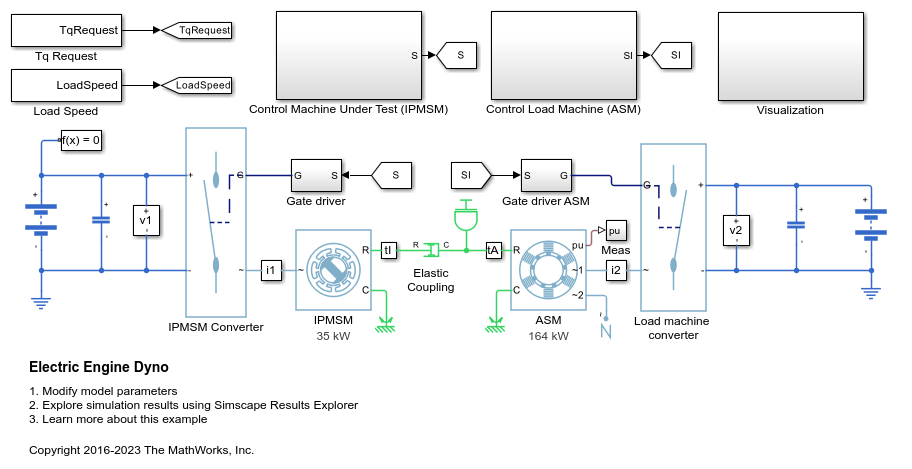
Electric Engine Dyno
Model an electric vehicle dynamometer test. The test environment contains an asynchronous machine (ASM) and an interior permanent magnet synchronous machine (IPMSM) connected back-to-back through a mechanical shaft. Both machines are fed by high-voltage batteries through controlled three-phase converters. The 164 kW ASM produces the load torque. The 35 kW IPMSM is the electric machine under test. The Control Machine Under Test (IPMSM) subsystem controls the torque of the IPMSM. The controller includes a multi-rate PI-based control structure. The rate of the open-loop torque control is slower than the rate of the closed-loop current control. The task scheduling for the controller is implemented as a Stateflow® state machine. The Control Load Machine (ASM) subsystem uses a single rate to control the speed of the ASM. The Visualization subsystem contains scopes that allow you to see the simulation results.
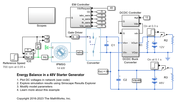
Energy Balance in a 48V Starter Generator
An interior permanent magnet synchronous machine (IPMSM) used as a starter/generator in a simplified 48V automotive system. The system contains a 48V electric network and a 12V electric network. The internal combustion engine (ICE) is represented by basic mechanical blocks. The IPMSM operates as a motor until the ICE reaches the idle speed and then it operates as a generator. The IPMSM supplies power to the 48V network, which contains the R3 power consumer. The 48V network supplies power to the 12V network which has two consumers: R1 and R2. The total simulation time (t) is 0.5 seconds. At t = 0.05 seconds, the ICE turns on. At t = 0.1 seconds, R3 switches on. At t = 0.3 seconds, R2 switches on and increases the load on the 12V electric network. The EM Controller subsystem includes a multi-rate PI-based cascade control structure which has an outer voltage-control loop and two inner current-control loops. The task scheduling in the Control subsystem is implemented as a Stateflow® state machine. The DCDC Controller subsystem implements a simple PI controller for the DC-DC Buck converter, which feeds the 12V network. The Scopes subsystem contains scopes that allow you to see the simulation results.
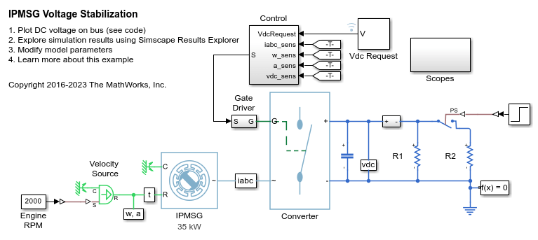
IPMSG Voltage Stabilization
Control an Interior Permanent Magnet Synchronous Generator (IPMSG) based low voltage generator system for a hybrid electric vehicle (HEV). The Control subsystem includes a multi-rate PI-based cascade control structure which has an outer voltage-control loop and two inner current-control loops. The task scheduling in the Control subsystem is implemented as a Stateflow® state machine. The Scopes subsystem contains scopes that allow you to see the simulation results. An ideal angular velocity source, which represents a combustion engine, drives the IPMSG. The IPMSG supplies low-voltage power to loads R1 and R2. At t = 0.4 seconds, the switch closes, increasing the load.
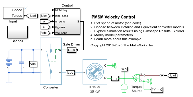
IPMSM Velocity Control
Control the rotor angular velocity in an interior permanent magnet synchronous machine (IPMSM) based automotive electrical-traction drive. A high-voltage battery feeds the IPMSM through a controlled three-phase converter. The IPMSM operates in both motoring and generating modes according to the load. An ideal torque source provides the load. The Scopes subsystem contains scopes that allow you to see the simulation results. The Control subsystem includes a multi-rate PI-based cascade control structure which has an outer angular-velocity-control loop and two inner current-control loops. The task scheduling in the Control subsystem is implemented as a Stateflow® state machine. During the one-second simulation, the angular velocity demand is 0 rpm, 500 rpm, 2000 rpm, and then 3000 rpm.
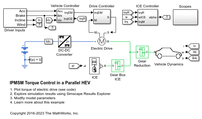
IPMSM Torque Control in a Parallel HEV
A simplified parallel hybrid electric vehicle (HEV). An interior permanent magnet synchronous machine (IPMSM) and an internal combustion engine (ICE) provide the vehicle propulsion. The IPMSM operates in both motoring and generating modes. The vehicle transmission and differential are implemented using a fixed-ratio gear-reduction model. The Vehicle Controller subsystem converts the driver inputs into torque commands. The vehicle control strategy is implemented as a Stateflow® state machine. The ICE Controller subsystem controls the torque of the combustion engine. The Drive Controller subsystem controls the torque of the IPMSM. The Scopes subsystem contains scopes that allow you to see the simulation results.
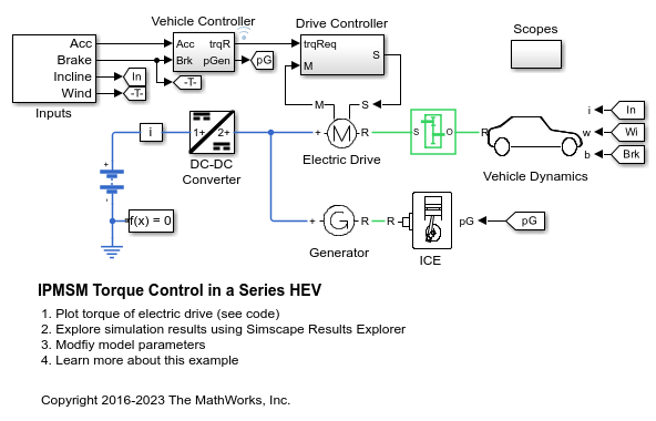
IPMSM Torque Control in a Series HEV
An interior permanent magnet synchronous machine (IPMSM) propelling a simplified series hybrid electric vehicle (HEV). An ideal DCDC converter, connected to a high-voltage battery, feeds the IPMSM through a controlled three-phase converter. A combustion engine driven generator charges the high-voltage battery. The vehicle transmission and differential are implemented using a fixed-ratio gear-reduction model. The Vehicle Controller subsystem converts the driver inputs into relevant commands for the IPMSM and generator. The Drive Controller subsystem controls the torque of the IPMSM. The controller includes a multi-rate PI-based control structure. The rate of the open-loop torque control is slower than the rate of the closed-loop current control. The task scheduling for the controller is implemented as a Stateflow® state machine. The Scopes subsystem contains scopes that allow you to see the simulation results.

IPMSM Torque Control in a Series-Parallel HEV
A simplified series-parallel hybrid electric vehicle (HEV). An interior permanent magnet synchronous machine (IPMSM) and an internal combustion engine (ICE) provide the vehicle propulsion. The ICE also uses electric generator to recharge the high-voltage battery during driving. The vehicle transmission and differential are implemented using a fixed-ratio gear-reduction model. The Vehicle Controller subsystem converts the driver inputs into torque commands. The vehicle control strategy is implemented as a Stateflow® state machine. The ICE Controller subsystem controls the torque of the combustion engine. The Generator Controller subsystem controls the torque of the electric generator. The Drive Controller subsystem controls the torque of the IPMSM. The Scopes subsystem contains scopes that allow you to see the simulation results.
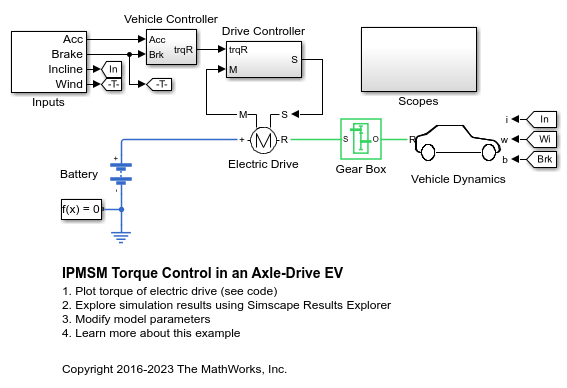
IPMSM Torque Control in an Axle-Drive HEV
An interior permanent magnet synchronous machine (IPMSM) propelling a simplified axle-drive electric vehicle. A high-voltage battery feeds the IPMSM through a controlled three-phase converter. The IPMSM operates in both motoring and generating modes. The vehicle transmission and differential are implemented using a fixed-ratio gear reduction model. The Vehicle Controller subsystem converts the driver inputs into a relevant torque command. The Drive Controller subsystem controls the torque of the IPMSM. The controller includes a multi-rate PI-based control structure. The rate of the open-loop torque control is slower than the rate of the closed-loop current control. The task scheduling for the controller is implemented as a Stateflow® state machine. The Scopes subsystem contains scopes that allow you to see the simulation results.
IPMSM Velocity Control
Control the rotor angular velocity in an interior permanent magnet synchronous machine (IPMSM) based automotive electrical-traction drive. A high-voltage battery feeds the IPMSM through a controlled three-phase converter. The IPMSM operates in both motoring and generating modes according to the load. An ideal torque source provides the load. The Scopes subsystem contains scopes that allow you to see the simulation results. The Control subsystem includes a multi-rate PI-based cascade control structure which has an outer angular-velocity-control loop and two inner current-control loops. The task scheduling in the Control subsystem is implemented as a Stateflow® state machine. During the one-second simulation, the angular velocity demand is 0 rpm, 500 rpm, 2000 rpm, and then 3000 rpm.
Ports
Input
Output
Parameters
References
[1] Haque, M. E., L. Zhong, and M. F. Rahman. "Improved trajectory control for an interior permanent magnet synchronous motor drive with extended operating limit." Journal of Electrical & Electronics Engineering. Vol. 22, Number 1, 2003, p. 49.
[2] Carpiuc, S., C. Lazar, and D. I. Patrascu. "Optimal Torque Control of the Externally Excited Synchronous Machine." Control Engineering and Applied Informatics. Vol. 14, Number 2, 2012, pp. 80–88.
Extended Capabilities
Version History
Introduced in R2017b