IPMSM Velocity Control
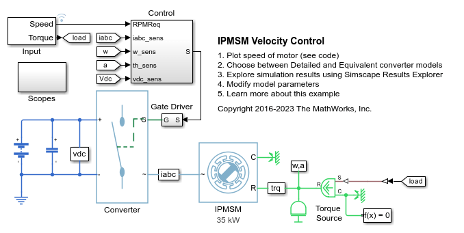
This example shows how to control the rotor angular velocity in an interior permanent magnet synchronous machine (IPMSM) based automotive electrical-traction drive. A high-voltage battery feeds the IPMSM through a controlled three-phase converter. The IPMSM operates in both motoring and generating modes according to the load. An ideal torque source provides the load. The Scopes subsystem contains scopes that allow you to see the simulation results. The Control subsystem includes a multi-rate PI-based cascade control structure which has an outer angular-velocity-control loop and two inner current-control loops. The task scheduling in the Control subsystem is implemented as a Stateflow® state machine. During the one-second simulation, the angular velocity demand is 0 rpm, 500 rpm, 2000 rpm, and then 3000 rpm.
Model
Simulation Results from Simscape Logging
The plot below shows the requested and measured speed for the test, as well as the phase currents in the electric drive.
See Also
PMSM | Converter (Three-Phase)