Author and Simulate Basic Colors Sequence Diagram with Enumerations
This example shows how to author and simulate a sequence diagram containing a variable of data type Simulink.IntEnumType
.
Define BasicColors.m
Enumeration
Create an enumeration
class called BasicColors
. Define Red(0)
, Yellow(1)
, and Blue(2)
as the enumerated values.
classdef BasicColors < Simulink.IntEnumType enumeration Red(0) Yellow(1) Blue(2) end
Open Enumeration Example Model
Open the EnumExample.slx
architecture model that contains a sequence diagram that implements the BasicColors
enumeration.
model = systemcomposer.openModel("EnumExample");
To inspect the Stateflow® Chart (Stateflow) block, double-click the source
component.
The output data port, data
, is typed by the BasicColors
enumeration in this state chart, where the color changes from Red
to Yellow
as the model simulates.
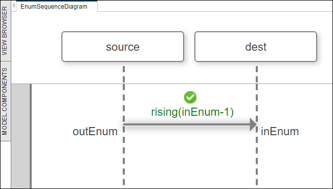
Open Enumeration Sequence Diagram
To open the Architecture Views Gallery and access the EnumSequenceDiagram
sequence diagram, go to Modeling > Sequence Diagram. To simulate the sequence diagram, click Run.
As the inEnum
destination port inherits a value of 1
from the BasicColors
enumeration, indicating a change from Red (0)
to Yellow (1)
, the sequence diagram executes successfully.
See Also
Tools
Functions
Objects
Related Topics
- Describe System Behavior Using Sequence Diagrams
- Describe System Behavior Using Activity Diagrams
- Pivot Between Lifelines and Components in Views Gallery
- Compose Architectures Visually
- Implement Component Behavior Using Simulink
- Implement Component Behavior Using Stateflow Charts
- Implement Component Behavior Using Simscape