使用活动图描述系统行为
活动图描述系统行为,它通过受控动作序列对从输入到输出的令牌流进行建模。活动图包含动作节点,这些节点的引脚由流程线连接。
操作是活动的构建模块,描述活动执行时发生的事情。每个动作都可以接受输入并产生输出,这些输出被称为令牌。
使用活动图构思系统,通过动作或决策可视化功能流,并了解系统组件如何交互。
您可以使用分配编辑器将活动图的元素分配到 System Composer™ 架构模型的元素中,从而更全面地描述您的功能架构设计。有关详细信息,请参阅移动机器人的设计架构和活动图。
这些概念与编写活动图相关:
令牌是在活动图中流动的对象。令牌可以表示结构体和整数等数据,也可以简单地传递控制信号。
令牌有两种类型:
对象令牌 - 表示一个对象,如一段数据
控制令牌 - 表示无数据载体的控制或触发事件
活动图中的流连接两个节点。虚线表示控制流。实线表示对象流。
流有两种类型:
对象流 - 对象流中的令牌包含动作操作的令牌数据。您可以使用对象流来路由输入或输出令牌,以便在对象节点之间传输信息或实体物品。
控制流 - 控制流中的令牌会触发执行操作。您可以使用控制流来建模从一个 Action Node 到另一个 Action Node 的控制转移。
动作节点是活动图中的一个关键构件。动作节点表示要执行的动作。动作节点消耗输入令牌,并在引脚上产生输出令牌。
使用 MATLAB® 函数或嵌套活动图来描述动作节点的行为。
控制节点是令牌通过系统的逻辑流的路由。
使用控制节点和流来路由令牌。控制节点可用于初始化、拆分、合并和终止令牌流。
以下是活动中的各种控制节点:
Initial Node - 在活动开始时发送一个控制令牌。
Decision or Merge Node - 决策节点根据对保护表达式的评估,将输入令牌路由到输出流。合并节点将来自多个输入流的令牌路由到单个输出流。合并决策节点根据守卫表达式的评估,将来自多个输入流的令牌路由到特定的输出流。
Join or Fork Node - 联合节点将多个输入令牌整合到一个输出流中,前提是每个输入引脚都有可用的令牌。分叉节点在每个输出流上复制一个输入令牌。
Flow Final Node - 终止一个对象或控制流,但不终止整个活动。
Activity Final Node - 终止传入的令牌和整个活动。
引脚充当对象令牌的缓冲区,引导令牌进入或离开动作节点。引脚的方向性代表输入或输出。您可以通过对象流连接引脚。
使用引脚将对象令牌路由到 Action Node 或从 Action Node 路由对象令牌。引脚还可用于在执行前或执行过程中存储对象令牌。您只能在对象流中使用引脚。
类型定义流经引脚的令牌内容。类型具有维度、单位、复杂度、最小值、最大值和描述。
活动图中有三种令牌类型:
值类型:值类型指分配给单个值的类型。
组合类型:组合类型相当于包含不同值和数据类型字段的总线结构。
MATLAB 类类型:MATLAB 类类型引用路径上的 MATLAB 类,该类定义一个具有属性和方法的复杂对象。您可以使用内置的 MATLAB 类,也可以定义自己的 MATLAB 类。有关使用 MATLAB 类类型的更多信息,请参阅使用 MATLAB 类令牌在活动图中建模复杂对象。
参数节点路由令牌进入或离开嵌套活动图。创建引脚时,会在嵌套活动中创建相应的参数节点。
使用参数节点定义令牌进入或离开嵌套活动的方式。参数节点有输入和输出两种类型。
创建新活动图
启动 System Composer 开始页面,创建活动图。在 MATLAB 命令行窗口中输入以下命令。
systemcomposer
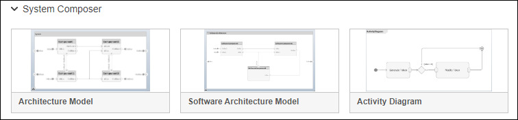
在弹出的对话框中,选择活动图。
或者,您可以使用 systemcomposer.createActivity 函数创建一个新的活动图。
编写、仿真并可视化活动图
活动图与架构模型在 System Composer 中集成。在设计系统时,您可以使用活动图来概念化系统,并可视化操作或决策的流程。活动图可帮助您理解系统元素之间的交互方式。在 System Composer 中,您还可以仿真和可视化活动图以验证系统行为。
| 主题 | 描述 |
|---|---|
| 编写活动图 | 交互式创建和编辑活动图,学习术语。 |
| 仿真、可视化和验证活动图 | 仿真和可视化活动图以验证系统行为。 |
提示
要了解更多关于 System Composer 概念在系统工程设计中的应用,请参阅System Composer 概念。
另请参阅
函数
工具
模块
- Initial Node | Action Node | Pin | Parameter Node | Decision or Merge Node | Join or Fork Node | Flow Final Node | Activity Final Node