编写活动图
活动图描述了架构系统的功能流行为。您可以在系统设计的早期阶段使用活动图来详细阐述最终系统目标。要创建活动图,请参阅创建新活动图。
活动图描述系统行为,它通过受控动作序列对从输入到输出的令牌流进行建模。活动图包含动作节点,这些节点的引脚由流程线连接。
使用活动图构思系统,通过动作或决策可视化功能流,并了解系统组件如何交互。
本主题介绍如何检查活动图的不同部分,以及如何编写每个节点以描述移动机器人沿随机生成的路径行进。您将学习如何:
在活动图中开始令牌流。您将使用一个初始节点和一个控制流。
在活动图中表示动作。
创建一个具有 MATLAB® 函数行为的动作节点。
创建一个包含嵌套活动的动作节点。
使用不带 MATLAB 函数的 MATLAB 动作节点来初始化对象令牌。
使用控制节点来操作令牌流。
使用分叉节点在两个控制流中复制控制令牌。
使用决策节点将输入令牌路由到其中一个输出流。
使用控制节点创建循环。
使用令牌并通过流程终止节点和活动终止节点终止活动。
您可以使用分配编辑器将活动图的元素分配到 System Composer™ 架构模型的元素中,从而更全面地描述您的功能架构设计。有关详细信息,请参阅移动机器人的设计架构和活动图。
有关活动图主题的路线图,请参阅使用活动图描述系统行为。
打开移动机器人的活动图功能流程
此示例显示了用于建模在随机起点和目的地之间移动的移动机器人架构的功能流程图。
打开工程。
openProject("scMobileRobotExample");打开活动图。
systemcomposer.openModel("RobotActivity");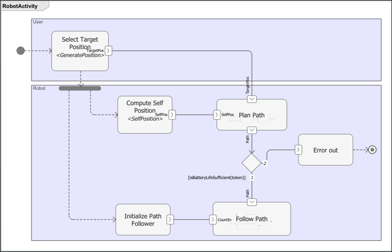
首先,机器人软件计算路径距离。如果距离超过机器人电池的续航能力,令牌将流向 Error out,活动终止。否则,机器人将沿路径前进。
活动图中的令牌流
令牌是在活动图中流动的对象。令牌可以表示结构体和整数等数据,也可以简单地传递控制信号。
令牌有两种类型:
对象令牌 - 表示一个对象,如一段数据
控制令牌 - 表示无数据载体的控制或触发事件
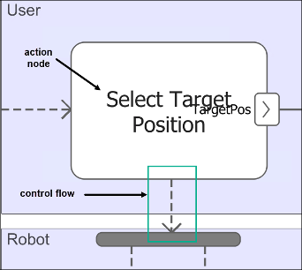
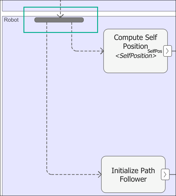
要开始活动,请使用 Initial Node 将控制令牌放置在单个流出流上。

活动图中的流连接两个节点。虚线表示控制流。实线表示对象流。
流有两种类型:
对象流 - 对象流中的令牌包含动作操作的令牌数据。您可以使用对象流来路由输入或输出令牌,以便在对象节点之间传输信息或实体物品。
控制流 - 控制流中的令牌会触发执行操作。您可以使用控制流来建模从一个 Action Node 到另一个 Action Node 的控制转移。
点击初始节点的右侧,然后拖动以生成控制流。然后,使用矩形框选取要实例化的动作节点。控制流将控制令牌传输到动作节点,并开始执行。
编写活动图动作节点
在活动图中,您可以使用 Action Node 生成令牌和读取令牌。
动作节点是活动图中的一个关键构件。动作节点表示要执行的动作。动作节点消耗输入令牌,并在引脚上产生输出令牌。
使用 MATLAB 函数或嵌套活动图来描述动作节点的行为。
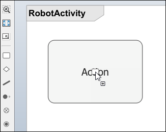
您可以通过点击并拖动左侧面板中的动作节点 ![]() 图标到画布中,在活动图中添加一个动作节点。
图标到画布中,在活动图中添加一个动作节点。
编写带有 MATLAB 函数行为的动作节点
具有 MATLAB 函数行为的活动图的第一个动作节点决定了开始动作的控制令牌如何在动作节点输出引脚上生成对象令牌。
引脚充当对象令牌的缓冲区,引导令牌进入或离开动作节点。引脚的方向性代表输入或输出。您可以通过对象流连接引脚。
使用引脚将对象令牌路由到 Action Node 或从 Action Node 路由对象令牌。引脚还可用于在执行前或执行过程中存储对象令牌。您只能在对象流中使用引脚。
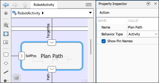
要实现 MATLAB 函数的行为,在属性检查器中,将行为类型设置为 MATLAB。然后,在 MATLAB 函数名称文本框中,输入函数的名称。
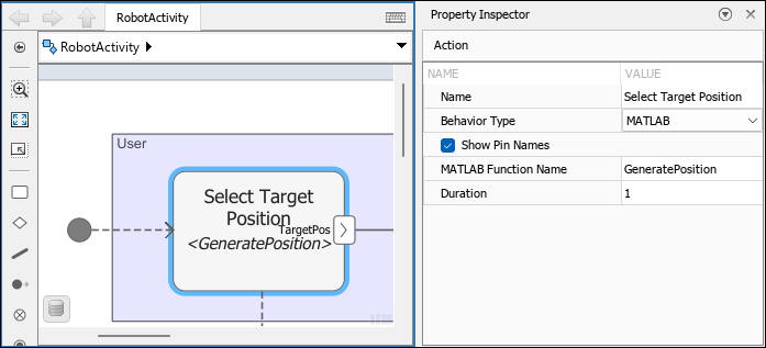
要在 MATLAB 编辑器中查看 GeneratePosition.m 函数文件,请双击 Select Target Position 动作节点。
function [TargetPos] = GeneratePosition()

close all;
figure('Name','RobotPath');
set(gca, 'XLim', [0 100], 'YLim', [0 100]);
hold on;

pos = randi(100, [1 2]);
TargetPos(1) = pos(1); % x
TargetPos(2)= pos(2); % y
TargetPos(3) = floor(rand*360); % orientation

plot(pos(1), pos(2), 'go', 'MarkerSize', 12);

end
GeneratePosition 函数计算移动机器人在图形上的随机起始位置和终止位置。GeneratePosition 函数不包含输入参量,只有一个输出参量。输出参量 TargetPos 对应于动作节点的输出引脚,表示一个三维向量,该向量包含机器人的起始位置、终止位置和方向。
要在动作节点上创建引脚,请在动作节点的边缘暂停,然后点击蓝色引脚。选择创建输入引脚还是输出引脚。

类型定义流经引脚的令牌内容。类型具有维度、单位、复杂度、最小值、最大值和描述。
活动图中有三种令牌类型:
值类型:值类型指分配给单个值的类型。
组合类型:组合类型相当于包含不同值和数据类型字段的总线结构。
MATLAB 类类型:MATLAB 类类型引用路径上的 MATLAB 类,该类定义一个具有属性和方法的复杂对象。您可以使用内置的 MATLAB 类,也可以定义自己的 MATLAB 类。有关使用 MATLAB 类类型的更多信息,请参阅使用 MATLAB 类令牌在活动图中建模复杂对象。
您可以选择 TargetPos 引脚,并在类型编辑器中查看其类型,以查看具有预期维度 PositionData 的相应 [1,3] 类型。
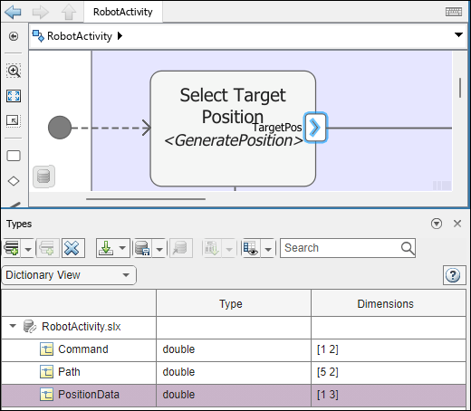
注意
当您将维度设置为 3 时,类型编辑器会自动将维度解释为列向量 [1,3]。
将动作节点引脚与 MATLAB 函数参量匹配
当函数文件 MATLAB 中的输入和输出参量与动作节点上的输入和输出引脚相匹配时,您可以使用链接的函数 MATLAB 来控制动作节点的预期行为。
在动作节点上,在属性检查器中,选择行为类型作为 MATLAB,然后链接到路径上的 MATLAB 函数文件。
右键点击动作节点,从上下文菜单中选择菜单选项将动作引脚匹配到 MATLAB 函数参量。
动作节点上的输入和输出引脚的名称和编号与链接的 MATLAB 函数中的输入和输出参量的名称和编号相匹配。
使用嵌套活动描述动作
您可以在活动图中将动作节点表示为嵌套活动。您使用嵌套活动描述的操作只能按顺序执行,无法同时执行多个实例。
当一个动作开始时,该动作的一个实例将执行,如果收到新的令牌,它们将在输入引脚中等待。输入引脚是一个队列。输入引脚的属性检查器中的令牌多重性参数决定了队列的大小。
要实现嵌套活动,在属性检查器中,将行为类型设置为活动。然后,要编写嵌套活动,请双击动作节点。
参数节点路由令牌进入或离开嵌套活动图。创建引脚时,会在嵌套活动中创建相应的参数节点。
使用参数节点定义令牌进入或离开嵌套活动的方式。参数节点有输入和输出两种类型。
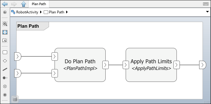
嵌套活动 Plan Path 根据串联连接的动作节点 Do Plan Path 和 Apply Path Limits 上的MATLAB 函数行为正常执行。路径规划以步骤计算路径:
将机器人调整至起始位置。
将机器人移动到 x-方向。
将机器人从 x-方向转向 y-方向。
将机器人移动到 y-方向。
将机器人调整至最终位置。
使用 MATLAB 动作节点(不带 MATLAB 函数)初始化对象令牌
当您编写活动图并在动作节点上的对象引脚之间连接流程线以描述动作序列时,可以使用不带任何 MATLAB 函数的 MATLAB 动作。
注意
对于未定义 MATLAB 函数的动作节点,将在输出引脚上创建一个默认令牌,其所有属性均设置为 0。
行为类型设置为 MATLAB 的 Initialize Path Follower 动作节点没有定义的 MATLAB 函数名称。您可以指定输出引脚类型,以初始化下一个动作节点的对象令牌类型。
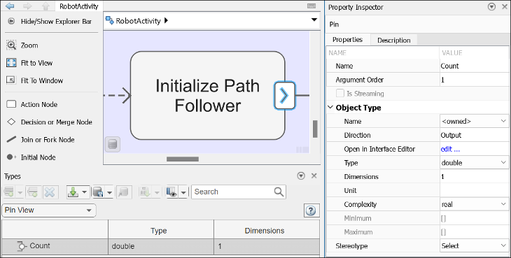
输出引脚存储一个令牌,该令牌沿流线传递到下一个动作节点输入引脚。对于 Initialize Path Follower 动作节点,将输出引脚 Count 的类型指定为拥有类型,类型为 double,维度为 1。
注意
在类型编辑器中初始化数据类型时,选项包括定点和枚举。由于支持有限,编译时检查已启用。使用 Ctrl+D 编译活动图,以验证数据类型。
使用动作节点生成控制流
要从动作节点生成控制流,请点击节点侧面,然后将其拖动到其他节点。
使用控制节点操作令牌流
控制节点是令牌通过系统的逻辑流的路由。
使用控制节点和流来路由令牌。控制节点可用于初始化、拆分、合并和终止令牌流。
使用分支节点拆分控制流
当作为分叉节点实现时,Join or Fork Node 节点在每个输出流上复制一个输入控制令牌。
控制流将控制令牌传输到两个不同的动作节点,并开始执行。
使用决策节点创建条件流程
A Decision or Merge Node 在作为决策节点实现时,根据决策条件的评估结果将输入令牌路由到特定的输出流。使用决策节点来操作令牌流,以演示此场景:当电池电量足以让机器人沿计算出的路径行驶时,机器人即可沿路径行驶。
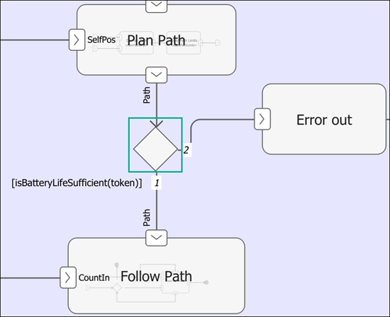
当函数 isBatteryLifeSufficient 从内置变量 true 中取当前令牌值后,评估结果为 token 时,令牌继续到 Follow Path 动作节点。否则,令牌将被路由到 Error out 动作节点。
要访问流中的令牌,请使用内置关键字 token。当 isBatteryLifeSufficient(token) 函数的评估结果为 true 时,令牌继续执行 Follow Path 动作节点。当 isBatteryLifeSufficient(token) 函数的评估结果为 false 时,令牌将被路由到 Error out 动作节点。
使用决策节点和合并节点创建循环
当您有一个使用计数变量来跟踪完成之前循环次数的迭代函数时,可以使用 Decision or Merge Node 将令牌路由到相同的动作节点或从该节点路由出来。
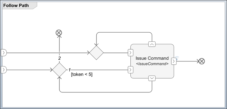
在此示例中,嵌套活动 Follow Path 包含一个 Issue Command 动作节点,该节点在移动机器人完成路径跟踪之前循环五次。
终止流程和活动与最终节点
您可以使用 Flow Final Node 终止一个对象或控件,但不能终止整个活动。Follow Path 活动图使用流程终止节点。您可以使用 Activity Final Node 来终止传入的令牌和父活动。
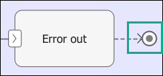
移动机器人路径规划出现错误后,活动通过活动最终节点结束。
仿真和验证活动图
现在您已经知道如何为移动机器人绘制跟随路径的活动图,可以仿真活动图以可视化令牌流。有关详细信息,请参阅仿真、可视化和验证活动图。
另请参阅
函数
工具
模块
- Initial Node | Action Node | Pin | Parameter Node | Decision or Merge Node | Join or Fork Node | Flow Final Node | Activity Final Node