以编程方式构建架构模型
使用 System Composer™ 以编程方式构建架构模型。
要构建模型,需添加包含数据接口、数据元素、值类型和物理接口的数据字典,然后添加组件、端口和连接。创建带有构造型和属性的配置文件,然后将这些构造型应用于模型元素。为端口分配专属接口。模型构建完成后,您可以创建自定义视图来关注特定的考虑因素。您还可以查询模型,根据指定的准则收集不同的模型元素。
添加组件、端口、连接和接口
创建一个模型并提取其架构。
model = systemcomposer.createModel("mobileRobotAPI");
arch = model.Architecture;
创建一个数据字典并添加一个数据接口。向该数据接口添加一个数据元素。向数据字典中添加一个值类型。将数据元素的类型指定为该值类型。添加一个物理接口和带有物理域类型的物理元素。将数据字典链接到模型。
dictionary = systemcomposer.createDictionary("SensorInterfaces.sldd");
interface = dictionary.addInterface("GPSInterface");
element = interface.addElement("SignalStrength");
valueType = dictionary.addValueType("SignalStrengthType",Units="dB", ...
    Description="GPS Signal Strength");
element.setType(valueType);
physicalInterface = dictionary.addPhysicalInterface("PhysicalInterface");
physicalElement = addElement(physicalInterface,"ElectricalElement", ...
    Type="electrical.electrical");
linkDictionary(model,"SensorInterfaces.sldd");
保存对数据字典的更改。
dictionary.save
保存模型。
model.save
打开模型。
systemcomposer.openModel("mobileRobotAPI");在接口编辑器中查看接口。

添加组件、端口和连接。将物理接口设置为稍后要连接的物理端口。
componentSensor = addComponent(arch,"Sensor");
sensorPorts = addPort(componentSensor.Architecture,{'MotionData','SensorPower'}, ...
    {'in','physical'});
sensorPorts(2).setInterface(physicalInterface)

componentPlanning = addComponent(arch,"Planning");
planningPorts = addPort(componentPlanning.Architecture, ...
    {'Command','SensorPower1','MotionCommand'}, ...
    {'in','physical','out'});
planningPorts(2).setInterface(physicalInterface)

componentMotion = addComponent(arch,"Motion");
motionPorts = addPort(componentMotion.Architecture,{'MotionCommand','MotionData'}, ...
    {'in','out'});
在 MotionData 端口上创建一个专属接口。在专属数据接口下添加一个专属数据元素。为数据元素 Rotation 指定一个单位设置为 degrees 的值类型。
ownedInterface = motionPorts(2).createInterface("DataInterface");
ownedElement = ownedInterface.addElement("Rotation");
subInterface = ownedElement.createOwnedType(Units="degrees");
在接口编辑器中查看接口。选择 Motion 组件上的 MotionData 端口。在接口编辑器中,将视图从字典视图切换为端口接口视图。

使用接口规则和默认名称规则连接组件。接口规则会将共享同一接口的组件端口连接起来。默认情况下,名称规则会将共享相同名称的组件端口连接起来。
c_sensorData = connect(arch,componentSensor,componentPlanning,Rule="interface");
c_motionData = connect(arch,componentMotion,componentSensor);
c_motionCommand = connect(arch,componentPlanning,componentMotion);
添加和连接架构端口
在架构上添加一个架构端口。
archPort = addPort(arch,"Command","in");
connect 命令需要一个组件端口作为参量。先获取组件端口,然后进行连接。
compPort = getPort(componentPlanning,"Command");
c_Command = connect(archPort,compPort);
保存模型。
model.save
按 Ctrl+Shift+A 或使用以下命令整理布局。
Simulink.BlockDiagram.arrangeSystem("mobileRobotAPI"); 
创建和应用带有构造型的配置文件
配置文件是可以应用于任何模型的 XML 文件。您可以在配置文件中添加具有属性的构造型,然后在配置文件编辑器中用特定值来为这些属性赋值。除了 System Composer 的内置分析功能之外,构造型还可以帮助您优化系统的性能、成本和可靠性。
创建配置文件并添加构造型
创建一个配置文件。
profile = systemcomposer.createProfile("GeneralProfile");创建一个适用于所有元素类型的构造型。
elemSType = addStereotype(profile,"projectElement");为不同类型的组件创建构造型。您可以根据自己的设计需求选择适当的类型。
pCompSType = addStereotype(profile,"physicalComponent",AppliesTo="Component");
sCompSType = addStereotype(profile,"softwareComponent",AppliesTo="Component");
为连接创建一个构造型。
sConnSType = addStereotype(profile,"standardConn",AppliesTo="Connector");
添加属性
为构造型添加属性。您可以使用属性来捕获模型元素的元数据,并分析非功能性需求。在导入了该配置文件的任何模型中,这些属性都会被添加到应用了该构造型的所有元素中。
addProperty(elemSType,'ID',Type="uint8");
addProperty(elemSType,'Description',Type="string");
addProperty(pCompSType,'Cost',Type="double",Units="USD");
addProperty(pCompSType,'Weight',Type="double",Units="g");
addProperty(sCompSType,'develCost',Type="double",Units="USD");
addProperty(sCompSType,'develTime',Type="double",Units="hour");
addProperty(sConnSType,'unitCost',Type="double"',Units="USD");
addProperty(sConnSType,'unitWeight',Type="double",Units="g");
addProperty(sConnSType,'length',Type="double",Units="m");
保存配置文件
profile.save;
将配置文件应用到模型
将配置文件应用到模型。
applyProfile(model,"GeneralProfile");将构造型应用于组件。有些组件是物理组件,有些组件是软件组件。
applyStereotype(componentPlanning,"GeneralProfile.softwareComponent")
applyStereotype(componentSensor,"GeneralProfile.physicalComponent")
applyStereotype(componentMotion,"GeneralProfile.physicalComponent")
将连接器构造型应用于所有连接。
batchApplyStereotype(arch,'Connector',"GeneralProfile.standardConn");
将通用元素构造型应用于所有连接器和端口。
batchApplyStereotype(arch,'Component',"GeneralProfile.projectElement");
batchApplyStereotype(arch,'Connector',"GeneralProfile.projectElement");
为每个组件设置属性。
setProperty(componentSensor,'GeneralProfile.projectElement.ID','001');
setProperty(componentSensor,'GeneralProfile.projectElement.Description', ...
    'Central unit for all sensors');
setProperty(componentSensor,'GeneralProfile.physicalComponent.Cost','200');
setProperty(componentSensor,'GeneralProfile.physicalComponent.Weight','450');
setProperty(componentPlanning,'GeneralProfile.projectElement.ID','002');
setProperty(componentPlanning,'GeneralProfile.projectElement.Description', ...
    'Planning computer');
setProperty(componentPlanning,'GeneralProfile.softwareComponent.develCost','20000');
setProperty(componentPlanning,'GeneralProfile.softwareComponent.develTime','300');
setProperty(componentMotion,'GeneralProfile.projectElement.ID','003');
setProperty(componentMotion,'GeneralProfile.projectElement.Description', ...
    'Motor and motor controller');
setProperty(componentMotion,'GeneralProfile.physicalComponent.Cost','4500');
setProperty(componentMotion,'GeneralProfile.physicalComponent.Weight','2500');
将所有连接的属性设置为相同值。
connections = [c_sensorData c_motionData c_motionCommand c_Command];
for k = 1:length(connections)
    setProperty(connections(k),'GeneralProfile.standardConn.unitCost','0.2');
    setProperty(connections(k),'GeneralProfile.standardConn.unitWeight','100');
    setProperty(connections(k),'GeneralProfile.standardConn.length','0.3');
end
添加层次结构
在 Motion 组件内添加两个名为 Controller 和 Scope 的组件。定义端口。将组件连接到架构以及彼此之间,并应用连接器构造型。架构图中的层次结构可以为组件的内部行为提供更详细的描述。
motionArch = componentMotion.Architecture;

motionController = motionArch.addComponent('Controller');
controllerPorts = addPort(motionController.Architecture,{'controlIn','controlOut'}, ...
    {'in','out'});
controllerCompPortIn = motionController.getPort('controlIn');
controllerCompPortOut = motionController.getPort('controlOut');

motionScope = motionArch.addComponent('Scope');
scopePorts = addPort(motionScope.Architecture,{'scopeIn','scopeOut'},{'in','out'});
scopeCompPortIn = motionScope.getPort('scopeIn');
scopeCompPortOut = motionScope.getPort('scopeOut');

c_planningController = connect(motionPorts(1),controllerCompPortIn);
对于输出端口连接,可以指定目标数据元素。
c_planningScope = connect(scopeCompPortOut,motionPorts(2),DestinationElement="Rotation");
c_planningConnect = connect(controllerCompPortOut,scopeCompPortIn, ...
    "GeneralProfile.standardConn");
保存模型。
model.save
按 Ctrl+Shift+A 或使用以下命令整理布局。
Simulink.BlockDiagram.arrangeSystem("mobileRobotAPI/Motion");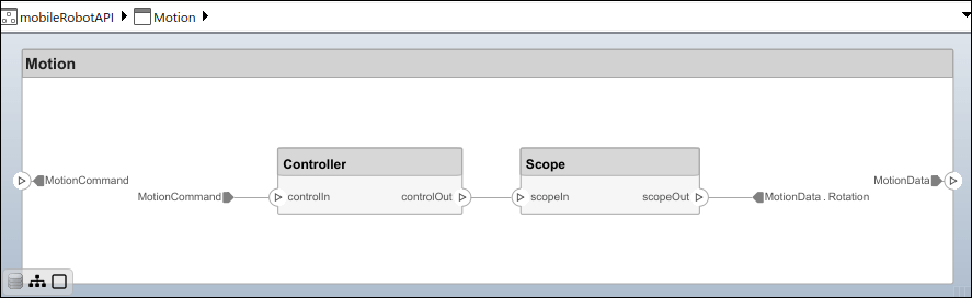
创建模型引用
模型引用可以帮助您按层次结构组织大型模型,并可实现对其架构和行为的一次定义,多次重用。当一个组件引用另一个模型时,该组件上的任何现有端口都会被删除,而引用模型上的端口会出现在该组件上。
创建一个新的 System Composer 模型。将 Controller 组件转换为引用组件,以引用新模型。要在 Controller 组件上添加端口,必须更新引用模型 mobileMotion。
referenceModel = systemcomposer.createModel("mobileMotion");
referenceArch = referenceModel.Architecture;
newComponents = addComponent(referenceArch,"Gyroscope");
referenceModel.save

linkToModel(motionController,"mobileMotion");

保存模型。
referenceModel.save
model.save
创建变体组件
您可以使用 makeVariant 函数将 Motion 组件转换为变体组件。原始组件会作为可选的变体选择项之一嵌入到变体组件中。您可以在变体组件中设计其他变体选择项,并切换活动选择项。变体组件允许您在架构模型中以编程方式选择不同的行为设计,从而进行权衡研究和分析。
[variantComp,choice1] = makeVariant(componentMotion);
添加一个名为 MotionAlt 的变体选择项。第二个参量定义名称,第三个参量定义标签。标签用于标识选择项。活动选择项由标签控制。
choice2 = addChoice(variantComp,{'MotionAlt'},{'MotionAlt'});在 MotionAlt 上创建所需的端口。
motionAltPorts = addPort(choice2.Architecture,{'MotionCommand','MotionData'},{'in','out'});将 MotionAlt 设置为活动变体。
setActiveChoice(variantComp,"MotionAlt")按 Ctrl+Shift+A 或使用以下命令整理布局。
Simulink.BlockDiagram.arrangeSystem("mobileRobotAPI/Motion");
保存模型。
model.save
清理
在再次运行此示例之前,请运行此脚本以删除生成的工件。
cleanUpArtifacts
另请参阅
函数
createModel|createDictionary|addInterface|addPhysicalInterface|addValueType|addElement|setType|createOwnedType|linkDictionary|addComponent|addPort|setInterface|connect|save|getPort|createProfile|addStereotype|addProperty|save|applyProfile|applyStereotype|batchApplyStereotype|setProperty|linkToModel|makeVariant|addChoice|setActiveChoice|closeAll