主要内容

MCPWM

R2026b

Generate PWM signals using the MCPWM peripheral on F28E12x C2000 processors

Since R2026b

  • MCPWM_block

Libraries:
C2000 Microcontroller Blockset / F28E12x

Description

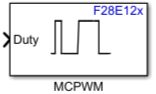
The MCPWM block controls the Multi-Channel Pulse Width Modulation (MCPWM) peripheral on Texas Instruments® F28E12x C2000™ processors to generate single or complementary PWM output signals for motor control, power conversion, and other switching applications.

The block accepts duty cycle values at each time step and writes them to the appropriate compare registers. Specify the duty cycle as a percentage or as raw timer counts. When you select both A and B outputs for a channel, the block accepts a two-element vector to independently control each output.

Ports

Input

expand all

Duty cycle for the selected PWM output, specified as a scalar or two-element vector. When you select a single output (such as PWM1A), provide a scalar. When you select both outputs (such as Both PWM1A and PWM1B), provide a two-element vector where the first element sets the A output and the second element sets the B output.

The block interprets the value as a percentage (0 to 100) or as raw timer counts, depending on the Duty cycle format in the model Configuration Parameters. Use uint16 for raw timer counts or single/double for percentage-based duty cycle values.

Dependencies

To enable this port, select the Add an input port to set duty ratio parameter.

Data Types: uint16 | single | double

Time base period for the MCPWM module counter, specified as a scalar. The block interprets this value as raw timer counts or seconds, depending on the timer period units in the model Configuration Parameters.

Dependencies

To enable this port, select the Add an input port to set PWM period parameter.

Data Types: uint16 | single

Phase direction for the time base counter, specified as a scalar. This value is written to the TBCTL.PHSDIR register bit on the hardware to control the counting direction after a synchronization event.

Dependencies

To enable this port, select the Add an input port to set phase shift parameter.

Data Types: uint16

Software synchronization pulse for the MCPWM module, specified as a scalar. Writing a nonzero value triggers a software sync event that loads the phase register value into the time base counter (TBCTL.SWSYNC).

Dependencies

To enable this port, select the Add an input port for software sync parameter.

Data Types: uint16

Continuous software force action for the selected PWM output, specified as a scalar or two-element vector. This value overrides the action qualifier output and forces the PWM pin to a specific state (low, high, or disabled) by writing to the AQSFRC register.

When you select both A and B outputs for a channel, provide a two-element vector where the first element controls the A output force action and the second element controls the B output force action.

Dependencies

To enable this port, select the Add an input port for continuous software force parameter.

Data Types: uint16

Parameters

expand all

Main

Select the MCPWM peripheral module.

MCPWM1

Uses the MCPWM1 module, which provides three PWM channel pairs (PWM1, PWM2, PWM3) with A and B outputs, plus CMPC and CMPD comparator outputs.

MCPWM3

Uses the MCPWM3 module, which provides one PWM channel pair (PWM1) with A and B outputs, plus CMPC and CMPD comparator outputs.

Programmatic Use

To set the block parameter value programmatically, use the set_param function.

Parameter: MCPWMModule
Values: 'MCPWM1' (default) | 'MCPWM3'
Data Types: char | string

Example: set_param(gcb,'MCPWMModule','MCPWM3')

When you select this parameter, the block adds the Period input port. Use this port to dynamically update the PWM time base period (TBPRD register) at each time step.

When this parameter is cleared, the block uses the fixed time base period configured in the model Configuration Parameters under Target hardware resources > MCPWM.

Programmatic Use

To set the block parameter value programmatically, use the set_param function.

Parameter: InportForPwmPeriod
Values: 'off' (default) | 'on'
Data Types: char | string

When you select this parameter, the block adds the Duty input port. Use this port to set the duty cycle for the selected PWM channel at each time step.

Programmatic Use

To set the block parameter value programmatically, use the set_param function.

Parameter: InportForDutyRatio
Values: 'on' (default) | 'off'
Data Types: char | string

When you select this parameter, the block adds the Sync input port. Use this port to trigger a software synchronization event that loads the phase register value into the time base counter.

Programmatic Use

To set the block parameter value programmatically, use the set_param function.

Parameter: InportForSoftwareSync
Values: 'off' (default) | 'on'
Data Types: char | string

Configure Channel

Select the PWM output channel. Each MCPWM module contains multiple PWM submodules with A and B outputs.

PWM1A, PWM2A, PWM3A

Drives only the A output of the specified PWM channel. The Duty input port accepts a scalar value.

PWM1B, PWM2B, PWM3B

Drives only the B output of the specified PWM channel. The Duty input port accepts a scalar value.

Both PWM1A and PWM1B, Both PWM2A and PWM2B, Both PWM3A and PWM3B

Drives both A and B outputs of the specified PWM channel. The Duty input port accepts a two-element vector.

CMPC, CMPD

Drives the CMPC or CMPD comparator output. The Duty input port accepts a scalar value representing the compare value.

Tips

  • PWM2 and PWM3 channels are available only on MCPWM1. MCPWM3 supports only PWM1 channels and CMPC/CMPD.

Programmatic Use

To set the block parameter value programmatically, use the set_param function.

Parameter: PinSelect
Values: 'PWM1A' (default) | 'PWM1B' | 'Both PWM1A and PWM1B' | 'PWM2A' | 'PWM2B' | 'Both PWM2A and PWM2B' | 'PWM3A' | 'PWM3B' | 'Both PWM3A and PWM3B' | 'CMPC' | 'CMPD'
Data Types: char | string

Example: set_param(gcb,'PinSelect','Both PWM1A and PWM1B')

When you select this parameter, the block adds the Phase input port. Use this port to dynamically control the phase direction (PHSDIR) of the time base counter after a synchronization event.

Programmatic Use

To set the block parameter value programmatically, use the set_param function.

Parameter: InportForPhaseShift
Values: 'off' (default) | 'on'
Data Types: char | string

When you select this parameter, the block adds the SFA input port. Use this port to apply a continuous software force action that overrides the normal action qualifier output, forcing the PWM pin to a specific state.

When you select both A and B outputs, provide a two-element vector to independently force each output.

Programmatic Use

To set the block parameter value programmatically, use the set_param function.

Parameter: InportForContinuousSoftwareForce
Values: 'off' (default) | 'on'
Data Types: char | string

Algorithms

At each time step, the block calls hardware-specific C functions to update the MCPWM peripheral registers:

C FunctionRegister UpdatedPurpose
updateCMP CMPxS Write compare values to the selected PWM channel
updateTBPRD TBPRDS Update time base period in raw counts
updateTBPRDFromSeconds TBPRDS Convert seconds to counts and update time base period
updatePHSDIR TBCTL.PHSDIR Set phase counting direction after sync
updateSWSYNC TBCTL.SWSYNC Trigger software synchronization pulse
updateSFRC AQSFRC Apply continuous software force action to outputs

When the timer period unit is set to seconds, the block converts the period value using the formula:

For up-count mode: TBPRD = (period_seconds * CPU_CLK) / prescaler_divider

For up-down count mode: TBPRD = (period_seconds * CPU_CLK) / (2 * prescaler_divider)

The CPU_CLK value comes from the system clock configuration, and prescaler_divider is set in Target hardware resources > MCPWM in the model Configuration Parameters.

Version History

Introduced in R2026b

expand all

See Also