External Interrupt Workflow for Texas Instruments C2000 Processors
This topic helps you with the workflow for external interrupts in a Simulink® model. To get started, perform these steps.
Create or open a Simulink model.
Add an C28x Hardware Interrupt block to the Simulink model.

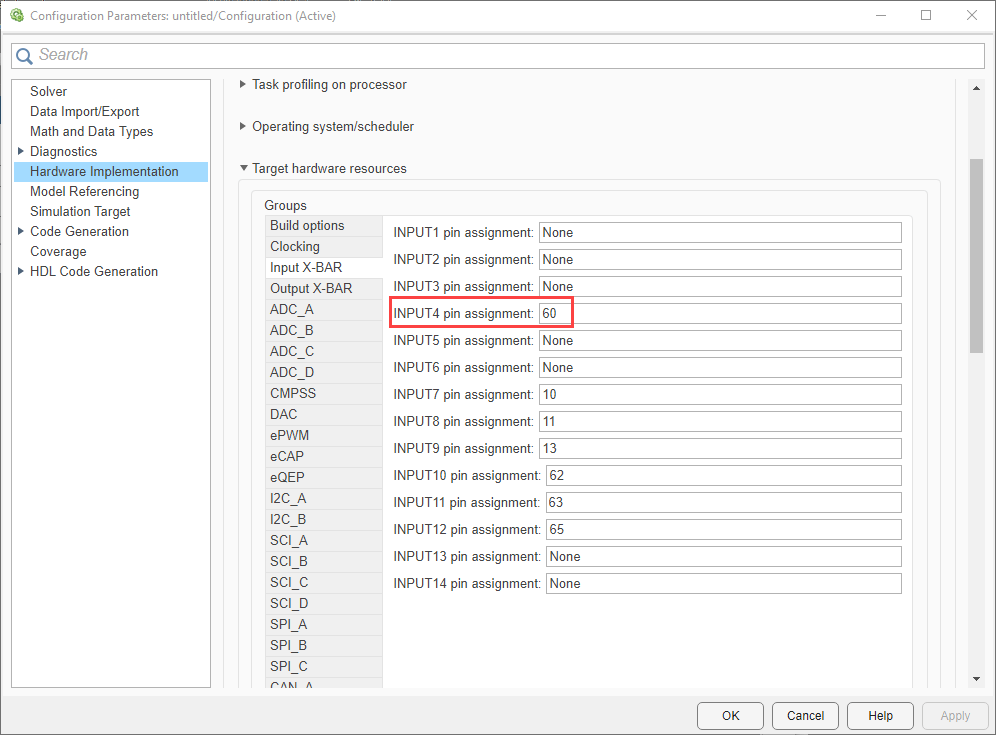
The hardware pin on which the interrupt is connected is specified in the Configuration Parameters dialog box. In the Simulink model, navigate to Modeling > Model Settings to open the Configuration Parameters dialog box. In the Configuration Parameters dialog box, navigate to Hardware Implementation > Target hardware resources > Input X-BAR.
For example, consider pin
60of F28379D Launch pad is used for external interrupt. Set INPUT4 pin assignment parameter value to60.
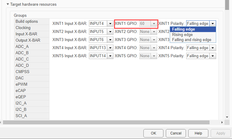
The interrupt pin is configured to detect rising, falling or both rising and falling edge. To configure, navigate to Configuration Parameters > Hardware Implementation > Target hardware resources > External interrupt.
The input pin 60 you selected earlier is reflected in XINT1 GPIO parameter. Select the required XINT1 Polarity.
Rising edge:This interrupt triggers when the pin voltage transitions from low to high voltage (0V to a positive voltage).Falling edge:This interrupt triggers when the pin voltage transitions from high to low voltage (positive voltage to 0V).Falling and rising edge:This interrupt triggers when the pin voltage transitions from low to high voltage (0V to a positive voltage) and high to low voltage (positive voltage to 0V).

Double-click the C28x Hardware Interrupt block to open the block parameters dialog.
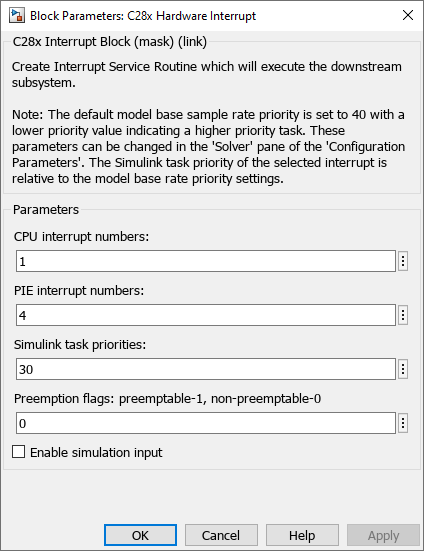
Specify the values for CPU interrupt numbers and PIE interrupt numbers parameters. For information on PIE and CPU interrupt numbers, see C28x Hardware Interrupt.
For the considered pin 60 example, PIE value is
4and CPU value is1as shown below.
Specify the Simulink task priorities and Preemption flags as required.

Add a Function-Call Subsystem block in the Simulink model.
The logic to be executed on the interrupt trigger is placed inside the function call subsystem.

Connect the output of External Interrupt block to the Function Call input of Function-Call Subsystem block.
In the Simulink model, navigate to Modeling > Model Settings to open the Configuration Parameters dialog box.
In the Configuration Parameters dialog box, navigate to Solver > Tasking and sample time options and then select Automatically handle rate transition for data transfer option. Click Apply and OK.
Note
If block with latched interrupts are placed inside the Function-Call Subsystem block, then follow the steps mentioned in Workaround to Reset Interrupt Pin of Sensors Supporting Latched Interrupts.