基于 C2000 处理器的永磁同步电机无传感器磁场定向控制
本例采用磁场定向控制 (FOC) 技术来控制三相永磁同步电机 (PMSM) 的速度。有关 FOC 的详细信息,请参阅磁场定向控制 (Motor Control Blockset)。
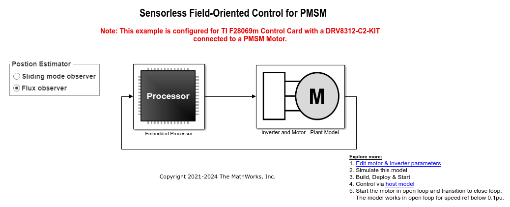
本例采用无传感器位置估计技术。您可以选择滑模观测器或磁通观测器来估计示例中使用的 FOC 算法的位置反馈。
采用闭环 FOC 算法来调节三相永磁同步电机的速度和转矩。本示例使用来自 C2000™ Microcontroller Blockset 的 C28x 外设模块和来自 Motor Control Blockset 的 MCB 库模块。
滑模观测器 (SMO) 模块在测量位置和估计位置之间的误差上产生滑动运动。该模块会生成一个与测量位置密切成比例的估计值。该模块使用定子电压 ![]() 和电流
和电流 ![]() 作为输入,并估计电机模型的电动势 (emf)。它利用电动势进一步估算转子位置和转子速度。Flux Observer 模块使用相同的输入
作为输入,并估计电机模型的电动势 (emf)。它利用电动势进一步估算转子位置和转子速度。Flux Observer 模块使用相同的输入 ![]() 来估计定子磁链、产生的转矩和转子位置。
来估计定子磁链、产生的转矩和转子位置。
所需硬件
此示例支持这些硬件配置。使用目标模型名称(以粗体突出显示)从 MATLAB® 命令提示符打开相应硬件配置的模型。
F28035 控制卡 + DRV8312-C2-KIT 逆变器:mcb_pmsm_foc_sensorless_f28035
F28335 控制卡 + DRV8312-C2-KIT 逆变器:mcb_pmsm_foc_sensorless_f28335
F28069m 控制卡 + DRV8312-C2-KIT 逆变器:mcb_pmsm_foc_sensorless_f28069m
LAUNCHXL-F280049C 控制器 + BOOSTXL-DRV8305 逆变器:mcb_pmsm_foc_sensorless_f280049C
F28027 LaunchPad + DRV8301/DRV8305EVM 逆变器:mcb_pmsm_foc_sensorless_f28027LaunchPad
F28069m 控制卡 + TMDSHVMTRINSPIN: mcb_pmsm_foc_sensorless_hvkit_f28069m
对于 LAUNCHXL-F28069M 控制器和 LAUNCHXL-F28379D 控制器,请参阅 PMSM 的无传感器磁场定向控制 (Motor Control Blockset)。
有关前面硬件配置的连接,请参阅 硬件连接。
可用模型
该示例包含以下模型:
注意:对于 LAUNCHXL-F28069M 控制器和 LAUNCHXL-F28379D 控制器,请参阅 PMSM 的无传感器磁场定向控制 (Motor Control Blockset)。
这些模型既可用于仿真,也可用于代码生成。打开 mcb_pmsm_foc_sensorless_f28069m 模型。
您可能需要更改模型参数以适应您的特定电机。使电机电压和功率特性与控制器相匹配。
传统的电压源逆变器驱动电机。控制器算法采用向量脉宽调制 (PWM) 技术,为六个功率开关器件生成六个脉宽调制 (PWM) 信号。逆变器使用两个模数转换器 (ADC) 测量电机的两个输入电流 (ia 和 ib),并将测量结果发送到处理器。
外设模块配置
设置此模型的外围模块配置。双击模块即可打开模块参数配置。如果想在其他硬件板上运行此示例,可以使用相同的参数值。
ePWM 模块配置

ADC 模块配置
本例中的算法采用异步调度。脉冲宽度调制 (PWM) 模块触发 ADC 转换。转换结束时,ADC 发出中断,触发主 FOC 算法。有关更多信息,请参考ADC Interrupt Based Scheduling。

配置模型
1.打开 mcb_pmsm_foc_sensorless_f28069m 模型。该模型专为 TI Piccolo F28069x 硬件配置。
2.要在其他 TI C2000 处理器上运行该模型,首先按 Ctrl+E 打开配置参数对话框。然后,通过导航至硬件实现>硬件板来选择所需的硬件板。
3.以下屏幕截图显示了模型中执行的调度器配置。如果想在其他硬件板上运行此示例,可以使用相同的参数值。

注意:
ADC 模块的采样率应与 ePWM 模块的 PWM 周期所确定的模型基准采样率相同。
基准触发频率的选择应与 ADC 模块触发的中断频率相同。有关更多信息,请参阅 Texas Instruments C2000 处理器的模型配置参数。
确保将默认参数行为(配置参数 > 代码生成 > 优化)设置为内联。
4.确保波特率设置为 5.625e6 比特/秒。

注意:
对于 F28335 处理器,您需要使用外部 FTDI 进行串行通信。
对于 F28035/F28335 处理器的无传感器示例,电机默认以每单位 0.5 的速度旋转。
必需的 MathWorks® 产品
仿真模型:
对于以下模型:mcb_pmsm_foc_sensorless_f28035 和 mcb_pmsm_foc_sensorless_f28335
Motor Control Blockset™
Fixed-Point Designer™
要生成代码并部署模型:
对于以下模型:mcb_pmsm_foc_sensorless_f28035 和 mcb_pmsm_foc_sensorless_f28335
Motor Control Blockset™
Embedded Coder®
C2000™ Microcontroller Blockset
Fixed-Point Designer™
前提条件
如果您从数据表或其他来源获取电机参数,请在与 Simulink® 模型关联的模型初始化脚本中更新电机参数和逆变器参数。有关说明,请参阅估计控制增益并调节控制参数 (Motor Control Blockset)。
仿真模型
此示例支持仿真。按照以下步骤仿真该模型。
1.打开此示例中包含的模型。
2.点击仿真选项卡上的运行按钮以仿真模型。
3.点击仿真选项卡上的数据检查器以查看和分析仿真结果。
在目标硬件上生成代码并运行模型
1.仿真目标模型并观察仿真结果。
2.完成硬件连接。
3.该模型自动计算模数转换器 (ADC) 或电流偏移值。要禁用此功能(默认启用),请在模型初始化脚本中将变量 inverter.ADCOffsetCalibEnable 的值更新为 0。
或者,您可以计算 ADC 偏移值,并在模型初始化脚本中手动更新它。有关说明,请参阅基于 C2000 处理器的三相交流电机开环控制。
4.打开您要使用的硬件配置的目标模型。如果要更改该模型的默认硬件配置设置,请参阅 模型配置参数 (Motor Control Blockset)。
5.在硬件选项卡上点击编译、部署和启动,将目标模型部署到硬件上。
6.在目标模型中,点击主机模型超链接以打开关联的主机模型。打开 mcb_pmsm_foc_host_model 模型:
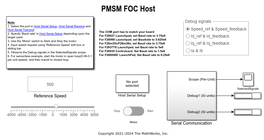
有关主机和目标模型之间串行通信的详细信息,请参阅 Host-Target Communication (Motor Control Blockset)。
7.将模型 mcb_pmsm_foc_host_model 中以下模块的 Port 参数设置为与主机 COM 端口匹配:
mcb_pmsm_foc_host_model > 主机串行设置。
mcb_pmsm_foc_host_model > 串行通信 > 主机串行接收。
mcb_pmsm_foc_host_model > 串行通信 > SCI_TX > 主机串行发送。
8.更新主机模型中的参考速度值。
注意:在以所需的参考速度运行电机之前(使用滑模观察器或磁通观察器),先使用开环控制以 0.1 x pmsm.N_base 的速度启动电机。然后通过将速度增加到 0.25 x pmsm.N_base 过渡到闭环控制(其中,pmsm.N_base 是电机基本速度的 MATLAB 工作空间变量)。
9.点击仿真选项卡上的运行来运行主机模型。
10.将电机开关的位置改为启动,使电机在开环状态下开始运行。
注意:不要让电机(以本例为例)长时间处于开环运行状态。电机可能会产生高电流和过多的热量。
我们设计的开环控制使电机的参考速度小于或等于基准速度的 10%。
当您在硬件上以较低的参考速度运行此示例时,由于已知问题,PMSM 可能不会跟随较低的参考速度。
11.将电机参考速度提高到基本速度的 10% 以上,即可从开环控制切换到闭环控制。
注意:要改变电机的旋转方向,请将电机参考速度降低到低于基准速度 10% 的值。这样就使电机恢复到开环状态。改变旋转方向,但保持参考速度的大小不变。然后过渡到闭环状态。
12.在主机模型的时间示波器中观察串行通信的调试信号。
其他可以尝试的操作
您可以使用 SoC Blockset™ 来实现无传感器闭环电机控制应用,该应用可以解决与 ADC-PWM 同步、控制器响应以及研究不同 PWM 设置相关的挑战。有关详情,请参阅用于多处理器 MCU 的分区电机控制。
您还可以使用 SoC Blockset™ 开发无传感器实时电机控制应用程序,该应用程序利用多个处理器内核来实现设计模块化、提高控制器性能以及其他设计目标。有关详情,请参阅Integrate MCU Scheduling and Peripherals in Motor Control Application。
对于 LAUNCHXL-F28069M 控制器和 LAUNCHXL-F28379D 控制器,请参阅 PMSM 的无传感器磁场定向控制 (Motor Control Blockset)。