Tune 3D Vector Field Histogram Controller for Obstacle Avoidance
Tune the parameters of a controllerVFH3D System object™ to navigate a multirotor UAV in an obstacle environment using a lidar sensor. Use the uavScenario object to create the obstacle environment. Mount a lidar sensor on the multirotor UAV to get the positions of obstacles. Use the uavWaypointFollower System object to set the goal location for the controllerVFH3D object. Use a PID controller to move the UAV in the desired obstacle-free direction.
Create Obstacle Scene Using UAV Scenario
Create a UAV scenario and set the simulation update rate to 2 Hz.
scene = uavScenario(UpdateRate=2);
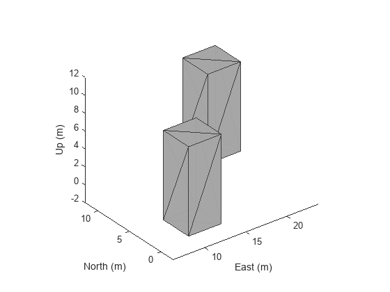
Add polygonal obstacle meshes to the scene.
polygonCorners1 = [8 -2;12 -2;12 2;8 2];
polygonCorners2 = [18 8;22 8;22 12;18 12];
polygonZRange = [0 10];
PolygonColor1 = [1 1 0];
PolygonColor2 = [0 0 1];
addMesh(scene,"polygon",{polygonCorners1,polygonZRange},PolygonColor1)
addMesh(scene,"polygon",{polygonCorners2,polygonZRange},PolygonColor2)
Visualize the scenario in 3D.
show3D(scene);
Create Multirotor Guidance Model and UAV Waypoint Follower
Create the multirotor UAV guidance model.
model = multirotor;
Create the waypoint follower. Set the UAV type, the transition radius for each waypoint, and the waypoints for the UAV to follow.
wf = uavWaypointFollower(UAVType="multirotor", ...
                         TransitionRadius=1, ...
                         Waypoints=[0 0 -5; 0 20 -5; 20 20 -5]);
Create UAV Platform and Mount Sensor
Specify the initial pose of the UAV.
uavPose = [0 0 -5 pi/2 0 0]';
Create a quadrotor platform using a north-east-down (NED) reference frame. Specify the initial position and orientation.
plat = uavPlatform("UAV",scene, ...
                   ReferenceFrame="NED", ...
                   InitialPosition=uavPose(1:3)', ...
                   InitialOrientation=eul2quat(uavPose(4:6)'));
Add a quadrotor mesh for visualization. Add a rotation to orient the mesh to the UAV body frame.
updateMesh(plat,"quadrotor",{1.5},[0 0 0],eul2tform([0 0 pi]))Create a statistical sensor model to generate point clouds for the lidar sensor.
lidarmodel = uavLidarPointCloudGenerator(AzimuthResolution=0.3324099, ...
                                         ElevationLimits=[-10 30], ...
                                         AzimuthLimits=[-60 60], ...
                                         ElevationResolution=0.5, ...
                                         MaxRange=10, ...
                                         UpdateRate=2, ...
                                         HasOrganizedOutput=true);
Create a lidar sensor, and mount the sensor on the quadrotor. Specify a mounting location for the sensor that is relative to the UAV body frame.
lidar = uavSensor("Lidar",plat,lidarmodel, ...
                  MountingLocation=[0 0 -0.4], ...
                  MountingAngles=[0 0 180]);
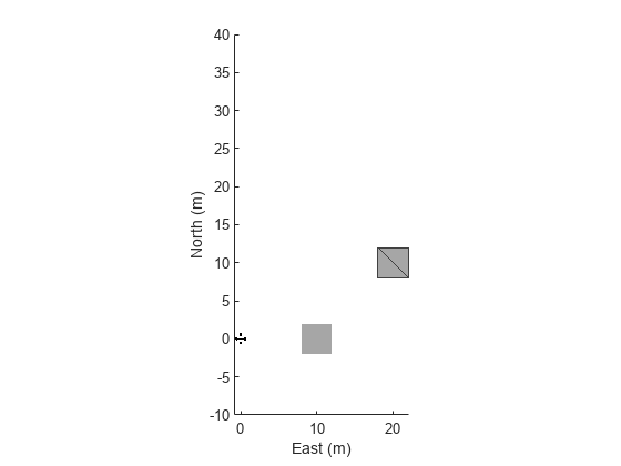
Set Up Simulation and Visualize Scenario
Visualize the scene. Remove edges from the floor mesh.
figure(1)
[ax,plotFrames] = show3D(scene);
ax.Children(end).LineStyle = "none";
Update the plot view for better visibility.
xlim(ax,[-10 40])
ylim(ax,[-10 40])
zlim(ax,[0 20])
view([-134.3 46.0])
axis(ax,"equal")
hold(ax,"on")
Configure controllerVFH3D Object and Integrate with Waypoint Follower
Create a controllerVFH3D object. Configure the HistogramResolution and MaxAge properties of the controllerVFH3D System object to improve obstacle avoidance. A low HistogramResolution value captures most of the obstacle points, but increases computation time. You can increase the MaxAge value to store obstacle points from previous time steps, enabling you to compute a stable obstacle-free direction, and better avoid local minima. Set the sensor-related parameters.
vfh3D = controllerVFH3D(HistogramResolution=5, ...
                        MaxAge=0, ...
                        HorizontalSensorFOV=lidarmodel.AzimuthLimits, ...
                        VerticalSensorFOV=lidarmodel.ElevationLimits, ...
                        SensorLocation=lidar.MountingLocation, ...
                        SensorOrientation=lidar.MountingAngles([3 2 1]));
The navigation logic uses two lookahead distances: one for the waypoint follower, and the other for the controllerVFH3D System object. The lookahead point for the waypoint follower is the target position for the controllerVFH3D System object. Compute the desired position for the PID controller from the desired direction output of the controllerVFH3D System object. A larger lookahead distance for the waypoint follower ensures that the target position is ahead of the desired position. This improves the tracking of the PID position controller.
Specify the lookahead distance for the desired point along an obstacle-free direction, and for the waypoint follower.
lookaheadOA = 2;
lookaheadWF = 6;
Set up the UAV initial state. The UAV state space consists of position, linear velocity, attitude Euler angles, angular velocity, thrust, and integral error.
uavPosition = uavPose(1:3);
uavOrientation = eul2quat(uavPose(4:6)')';
intErr = [0; 0; 0];
initialState = [uavPosition(1); uavPosition(2); uavPosition(3); ...
                0; 0; 0; uavPose(4); 0; 0; 0; 0; 0; 0; intErr];
Set the PID controller parameters.
kp = 15;
kd = 12;
ki = 0.005;
kyaw = 10;
Set the simulation start time, the number of simulation iterations, and the integration interval.
tStart = 0;
numIter = 200;
tStep = 0.1;
Create an empty time vector to store the time stamps of integration results
hStep = tStep/10;
tTotal = zeros(numIter*(tStep/hStep+1),1);
Create an empty states vector to store the simulation states. Number of states is equal to the number of model states plus integral error.
numStates = numel(model.state)+3;
states = zeros(numIter*(tStep/hStep+1),numStates);
Tune controllerVFH3D Object
To obtain the desired obstacle avoidance behavior, you must tune some of the properties of the controllerVFH3D System object.
Modify the obstacle avoidance algorithm behavior can be modified by changing the range sensor distance limits of the controllerVFH3D object.
vfh3D.DistanceLimits = [0.1 5];
Modify the path of the UAV by changing the weights associated with the target direction, previous direction, and desired direction.
vfh3D.TargetDirectionWeight = 5;
vfh3D.PreviousDirectionWeight = 2;
vfh3D.CurrentDirectionWeight = 2;
Modify the UAV radius and the safety distance properties to control the proximity of the UAV to the obstacles.
vfh3D.VehicleRadius = 0.5;
vfh3D.SafetyDistance = 0.5;
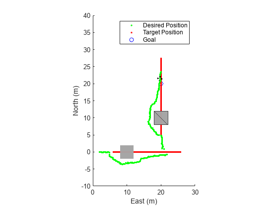
Simulate Obstacle Avoidance in UAV Scenario
Set up the simulation. Then, iterate through the positions and show the scene each time the lidar sensor updates. Advance the scene, move the UAV platform, and update the sensors.
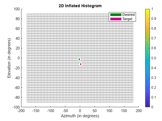
setup(scene)

for idx = 1:numIter
    [isupdated,lidarSampleTime,pt] = read(lidar);
    xLidar = reshape(pt.Location(:,:,1),[],1);
    yLidar = reshape(pt.Location(:,:,2),[],1);
    zLidar = reshape(pt.Location(:,:,3),[],1);

    sensorPoints = [xLidar yLidar zLidar];

    [targetPosition,~,~] = wf(uavPose(1:4),lookaheadWF);

    [desiredDirection,desiredYaw,status] = vfh3D(uavPosition,uavOrientation, ...
                                                 sensorPoints,targetPosition);

    % Visualize the histogram.
    figure(2)
    show(vfh3D,PlotsToShow="2D Inflated Histogram");

    % Select the desired position along the obstacle-free direction.
    desiredPosition = uavPosition + lookaheadOA*desiredDirection;

    [t,y] = ode23(@(t,x)exampleHelperDerivative(t,x,model,desiredPosition,desiredYaw,kp,kd,ki,kyaw), ...
                  tStart:hStep:(tStart+tStep),initialState);

    % Store data.
    tTotal((idx-1)*(tStep/hStep+1) + 1:idx*(tStep/hStep+1)) = t;
    states((idx-1)*(tStep/hStep+1) + 1:idx*(tStep/hStep+1),:) = y;

    % Update states.
    uavPosition = y(end,1:3)';
    uavOrientEul = y(end,7:9)';
    uavOrientation = eul2quat(uavOrientEul')';
    tStart = t(end);
    initialState = y(end,:);

    % Plot the path.
    desPosition = plot3(desiredPosition(2),desiredPosition(1),-desiredPosition(3),".g",Parent=ax);
    tgtPosition = plot3(targetPosition(2),targetPosition(1),-targetPosition(3),".r",Parent=ax);
    goalPosition = plot3(wf.Waypoints(end,2),wf.Waypoints(end,1),-wf.Waypoints(end,3),"ob",Parent=ax);
    legend(ax,[desPosition tgtPosition goalPosition],["Desired Position","Target Position","Goal"])


    if isupdated
        % Use fast update to move platform visualization frames.
        show3D(scene,Parent=ax,Time=lidarSampleTime,FastUpdate=true);

        % Move the platform.
        move(plat,[uavPosition' y(end,4:6) zeros(1,3) eul2quat(uavOrientEul') zeros(1,3)]);
        drawnow limitrate
    end

    % Advance the scene simulation time.
    advance(scene);

    % Update all sensors in the scene.
    updateSensors(scene)

    uavPose = [uavPosition; quat2eul(uavOrientation',"ZYX")'];
end
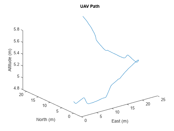
Visualize Path
Visualize the path of the UAV through the environment.
figure(3)
plot3(states(:,2),states(:,1),-states(:,3))
title("UAV Path")
xlabel("East (m)")
ylabel("North (m)")
zlabel("Altitude (m)")