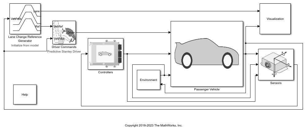
Dugoff Wheel 2DOF
Libraries:
Vehicle Dynamics Blockset /
Wheels and Tires
Description
The Dugoff Wheel 2DOF block implements a simplified tire with lateral and longitudinal slip capability based on the H. Dugoff model[1]. The block uses a translational friction model to calculate the forces and moments during combined longitudinal and lateral slip, requiring fewer parameters than the Combined Slip Wheel 2DOF block. If you do not have the tire coefficients needed by the Magic Formula, consider using this block for studies that do not involve extensive nonlinear combined lateral slip or lateral dynamics. If your study does require nonlinear combined slip or lateral dynamics, consider using the Combined Slip Wheel 2DOF block.
The block determines the wheel rotation rate, vertical motion, and forces and moments in all six degrees-of-freedom (DOFs) based on the driveline torque, brake pressure, road height, wheel camber angle, and inflation pressure. You can use this block for these types of analyses:
Driveline and vehicle simulations that require low frequency tire-road and braking forces for vehicle acceleration, braking, and wheel rolling resistance calculations with minimal tire parameters.
Wheel interaction with an idealized road surface.
Ride and handling maneuvers for vehicles undergoing mild combined slip. For this analysis, you can connect the block to driveline and chassis components such as differentials, suspension, and vehicle body systems.
Yaw stability. For this analysis, you can connect this block to more detailed braking system models.
Tire stiffness and unsprung mass interactions with ground variations, load transfer, or chassis motion using the block vertical DOF.
The block integrates rotational wheel, vertical mass, and braking dynamics models.
You can set your own user-defined model parameter values or use a built-in tire model.
If you install the Extended Tire Features for Vehicle Dynamics Blockset support package, these additional capabilities are available:
Plot generation — Click the Plot steady state force, moment response button to generate these plots:
Lateral force [N] vs Slip angle [rad]
Self-aligning moment [Nm] vs Slip angle [rad]
Longitudinal force [N] vs Longitudinal slip []
Longitudinal force [N] vs Lateral force [N]
Import tire parameters — Use the
tireModel.getmethod to import tire parameter values defined in the Dugoff Wheel 2DOF block to atireModelobject.Export tire parameters — Use the
setmethod to export tire parameter values from atireModelobject to the Dugoff Wheel 2DOF block.Tire model conversion — Use the
convertmethod to convert a tire model of one of these types to a Dugoff tire model that you can import to the Dugoff Wheel 2DOF block:Magic Formula 5.2
Magic Formula 6.2
Fiala
Use the Tire type parameter to either input tire parameter values or select a fitted tire parameter set.
| Goal | Action |
|---|---|
Input user-defined tire parameter values. | Update the block parameters with user-defined parameter values:
|
Select one of the built-in Dugoff tire models to drive the lateral and longitudinal calculations. [Link]. | Update the applicable block parameters with values from a built-in tire model:
|
Use the Model slip type parameter to select slip type.
| Action | Model Slip Type Setting |
|---|---|
Calculate longitudinal and lateral forces under nominal slip conditions | Nominal slip |
Calculate longitudinal and lateral forces with additional correction factors for a more accurate response at higher slip values | Extended slip |
Use the Brake Type parameter to select the brake.
| Action | Brake Type Setting |
|---|---|
No braking |
|
Implement brake that converts the brake cylinder pressure into a braking force |
|
Implement simplex drum brake that converts the applied force and brake geometry into a net braking torque |
|
Implement lookup table that is a function of the wheel speed and applied brake pressure |
|
To calculate the rolling resistance torque, specify one of these Rolling Resistance parameters.
| Setting | Block Implementation |
|---|---|
| None |
| Method in Stepwise Coastdown Methodology for Measuring Tire Rolling Resistance. The rolling resistance is a function of tire pressure, normal force, and velocity. |
| Method specified in ISO 28580:2018, Passenger car, truck and bus tyre rolling resistance measurement method — Single point test and correlation of measurement results. |
| Magic formula equations from 4.E70 in Tire and Vehicle Dynamics. The magic formula is an empirical equation based on fitting coefficients. |
| Lookup table that is a function of the normal force and spin axis longitudinal velocity. |
To calculate vertical motion, specify one of these Vertical Motion parameters.
| Setting | Block Implementation |
|---|---|
| Block passes the applied chassis forces directly through to the rolling resistance and longitudinal force calculations. |
| Vertical motion depends on wheel stiffness and damping. Stiffness is a function of tire sidewall displacement and pressure. Damping is a function of tire sidewall velocity and pressure. |
| The block uses the defined sidewall deflection directly in the effective radius calculation. |
Rotational Wheel Dynamics
The block calculates the inertial response of the wheel subject to:
Axle losses
Brake and drive torque
Tire rolling resistance
Ground contact through the tire-road interface
The input torque is the summation of the applied axle torque, braking torque, and moment arising from the combined tire torque.
For the moment arising from the combined tire torque, the block implements tractive wheel forces and rolling resistance with first-order dynamics. The rolling resistance has a time constant parameterized in terms of a relaxation length.
To calculate the rolling resistance torque, you can specify one of these Rolling Resistance parameters.
| Setting | Block Implementation |
|---|---|
| Block sets rolling resistance,
|
| Block uses the method in SAE Stepwise Coastdown Methodology for Measuring Tire Rolling Resistance. The rolling resistance is a function of tire pressure, normal force, and velocity, specifically: |
| Block uses the method specified in ISO 28580:2018, Passenger car, truck and bus tyre rolling resistance measurement method — Single point test and correlation of measurement results. The method accounts for normal load, parasitic loss, and thermal corrections from test conditions, specifically: |
| Block calculates the rolling resistance,
|
| For the rolling resistance,
|
If the brakes are enabled, the block determines the braking locked or unlocked condition based on an idealized dry clutch friction model. Based on the lock-up condition, the block implements these friction and dynamic models.
| Equation | Lock-Up Condition | Friction Model | Dynamic Model |
|---|---|---|---|
Unlocked | |||
Locked |
The equations use these variables.
| Variable | Value |
|---|---|
| ω | Wheel angular velocity |
| a | Velocity-independent force component |
| b | Linear velocity force component |
| c | Quadratic velocity force component |
| Le | Tire relaxation length |
| J | Moment of inertia |
| My | Rolling resistance torque |
| Ta | Applied axle torque |
| Tb | Braking torque |
| Td | Combined tire torque |
| Tf | Frictional torque |
| Ti | Net input torque |
| Tk | Kinetic frictional torque |
| To | Net output torque |
| Ts | Static frictional torque |
| Fc | Applied clutch force |
| Fx | Longitudinal force developed by the tire road interface due to slip |
| Reff | Effective clutch radius |
| Ro | Annular disk outer radius |
| Ri | Annular disk inner radius |
| Re | Effective tire radius while under load and for a given pressure |
| Vx | Longitudinal axle velocity |
| Fz | Vehicle normal force |
| Cr | Rolling resistance constant |
| Tamb | Ambient temperature |
| Tmeas | Measured temperature for rolling resistance constant |
| Fpl | Parasitic force loss |
| Kt | Thermal correction factor |
| ɑ | Tire pressure exponent |
| β | Normal force exponent |
| pi | Tire pressure |
| μs | Coefficient of static friction |
| μk | Coefficient of kinetic friction |
Longitudinal Force
The block implements the longitudinal force as a function of wheel slip relative to the road surface using these equations.
| Calculation | Equation |
|---|---|
Nominal Slip | |
Extended | |
Friction coefficient |
The equations use these variables.
| Variable | Value |
|---|---|
| Fx | Longitudinal force acting on axle along tire-fixed x-axis |
| Cκ | Longitudinal stiffness |
| Cα | Lateral stiffness per slip angle |
| k | Longitudinal slip ratio of tires |
| Fz | Vertical contact patch normal force along tire-fixed z-axis |
| u | Velocity component in the wheel plane |
| μ | Maximum friction coefficient |
| μ0 | Maximum friction scaling coefficient |
| As | Friction reduction factor |
| Vs | Friction reduction magnitude |
| α | Side slip angle of tires |
| gx | Longitudinal correction factor |
| gx1 | Longitudinal squared slip correction factor |
| gx2 | Longitudinal squared slip friction correction factor |
| gx3 | Longitudinal linear slip correction factor |
| gx4 | Longitudinal linear slip friction correction factor |
| gx5 | Longitudinal offset correction factor |
Lateral Force
The block implements the lateral force as a function of wheel slip angle state using these equations.
| Calculation | Equation |
|---|---|
Nominal Slip | |
Extended Slip | |
Friction Coefficient |
The equations use these variables.
| Variable | Value |
|---|---|
| α | Side slip angle of tires |
| Fy | Lateral force acting on axle along tire-fixed y-axis |
| Fz | Vertical contact patch normal force along tire-fixed z-axis |
| ɣ | Camber angle |
| Cɣ | Camber stiffness |
| Cα | Lateral stiffness per angle slip |
| Ck | Longitudinal stiffness |
| k | Longitudinal slip ratio of tires |
| u | Velocity component in the wheel plane |
| μ | Maximum friction coefficient |
| μ0 | Maximum friction scaling coefficient |
| Vs | Friction reduction magnitude |
| As | Friction reduction factor |
| gy | Lateral correction factor |
| gy1 | Lateral maximum friction correction factor |
| gy2 | Lateral offset correction factor |
Vertical Dynamics
The block implements these equations for the vertical dynamics.
| Calculation | Equation |
|---|---|
Vertical response | |
Tire normal force | |
Vertical sidewall deflection |
The equations use these variables.
| Variable | Value |
|---|---|
| z | Tire deflection along tire-fixed z-axis |
| zgnd | Ground displacement along tire-fixed z-axis |
| Fztire | Tire normal force along tire-fixed z-axis |
| Fz | Vertical force acting on axle along tire-fixed z-axis |
| ρz | Vertical sidewall deflection along tire-fixed z-axis |
| k | Vertical sidewall stiffness |
| b | Vertical sidewall damping |
Overturning, Aligning, and Scaling
This table summarizes the overturning, aligning, and scaling implementation.
| Calculation | Implementation |
|---|---|
Overturning moment | The Dugoff model does not define an overturning moment. The block implements this equation, requiring minimal parameters. |
Aligning moment | The block implements the aligning moment as a combination of yaw rate damping and slip angle state. |
Friction scaling | To vary the coefficient of friction, use the ScaleFctr input port. |
The equations use these variables.
| Variable | Value |
|---|---|
| Mx | Overturning moment acting on axle about tire-fixed x-axis |
| Mz | Aligning moment acting on axle about tire-fixed z-axis |
| Re | Effective contact patch to wheel carrier radial distance |
| ɣ | Camber angle |
| k | Vertical sidewall stiffness |
| b | Vertical sidewall damping |
Tire angular velocity about the tire-fixed z-axis (yaw rate) | |
| w | Tire width |
| α' | Slip angle state |
| bMz | Linear yaw rate resistance |
| Fy | Lateral force acting on axle along tire-fixed y-axis |
| Cɣ | Camber stiffness |
| Cα | Lateral stiffness per slip angle |
| μ | Friction coefficient |
| Fz | Vertical contact patch normal force along tire-fixed z-axis |
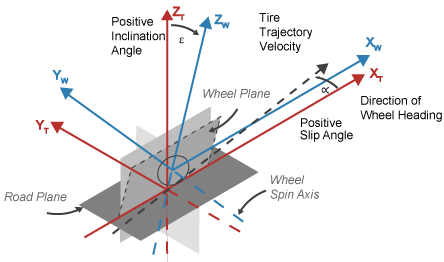
Tire and Wheel Coordinate Systems
To resolve the forces and moments, the block uses the Z-Up orientation of the tire and wheel coordinate systems.
Tire coordinate system axes (XT, YT, ZT) are fixed in a reference frame attached to the tire. The origin is at the tire contact with the ground.
Wheel coordinate system axes (XW, YW, ZW) are fixed in a reference frame attached to the wheel. The origin is at the wheel center.
Z-Up Orientation1
Brakes
If you specify the Brake Type parameter as
Disc, the block implements a disc brake. This figure
shows the side and front views of a disc brake.
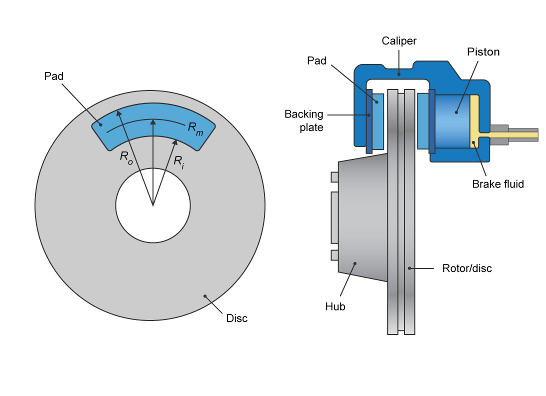
A disc brake converts brake cylinder pressure from the brake cylinder into force. The disc brake applies the force at the brake pad mean radius.
The block uses these equations to calculate brake torque for the disc brake.
The equations use these variables.
| Variable | Value |
|---|---|
| T | Brake torque |
| P | Applied brake pressure |
| N | Wheel speed |
| Npads | Number of brake pads in disc brake assembly |
| μstatic | Disc pad-rotor coefficient of static friction |
| μ | Disc pad-rotor coefficient of kinetic friction |
| Ba | Brake actuator bore diameter |
| Rm | Mean radius of brake pad force application on brake rotor |
| Ro | Outer radius of brake pad |
| Ri | Inner radius of brake pad |
If you specify the Brake Type parameter as
Drum, the block implements a static (steady-state)
simplex drum brake. A simplex drum brake consists of a single two-sided hydraulic
actuator and two brake shoes. The brake shoes do not share a common hinge pin.
The simplex drum brake model uses the applied force and brake geometry to calculate a net torque for each brake shoe. The drum model assumes that the actuators and shoe geometry are symmetrical for both sides, allowing a single set of geometry and friction parameters to be used for both shoes.
The block implements equations that are derived from these equations in Fundamentals of Machine Elements.
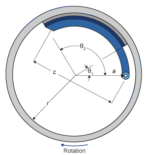
The equations use these variables.
| Variable | Value |
|---|---|
| T | Brake torque |
| P | Applied brake pressure |
| N | Wheel speed |
| μstatic | Disc pad-rotor coefficient of static friction |
| μ | Disc pad-rotor coefficient of kinetic friction |
| Trshoe | Right shoe brake torque |
| Tlshoe | Left shoe brake torque |
| a | Distance from drum center to shoe hinge pin center |
| c | Distance from shoe hinge pin center to brake actuator connection on brake shoe |
| r | Drum internal radius |
| Ba | Brake actuator bore diameter |
| Θ1 | Angle from shoe hinge pin center to start of brake pad material on shoe |
| Θ2 | Angle from shoe hinge pin center to end of brake pad material on shoe |
If you specify the Brake Type parameter as
Mapped, the block uses a lookup table to determine the
brake torque.
The equations use these variables.
| Variable | Value |
|---|---|
| T | Brake torque |
Brake torque lookup table | |
| P | Applied brake pressure |
| N | Wheel speed |
| μstatic | Friction coefficient of drum pad-face interface under static conditions |
| μ | Friction coefficient of disc pad-rotor interface |
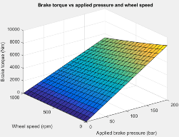
The lookup table for the brake torque, , is a function of applied brake pressure and wheel speed, where:
T is brake torque, in N·m.
P is applied brake pressure, in bar.
N is wheel speed, in rpm.
Examples
Ports
Input
Output
Parameters
References
[1] Bhoraskar, A. and P. Sakthivel. "A Review and a Comparison of Dugoff and Modified Dugoff Formula with Magic Formula." 2017 International Conference on Nascent Technologies in Engineering (ICNTE)(2017): 1–4. https://doi.org/10.1109/ICNTE.2017.7947898.
[2] Highway Tire Committee. Stepwise Coastdown Methodology for Measuring Tire Rolling Resistance. Standard J2452_199906. Warrendale, PA: SAE International, June 1999.
[3] International Organization for Standardization. Passenger car, truck and bus tyre rolling resistance measurement method — Single point test and correlation of measurement results. ISO 28580: 2018. https://www.iso.org/standard/67531.html.
[4] Pacejka, H. B. Tire and Vehicle Dynamics, 3rd ed. Oxford, UK: SAE and Butterworth-Heinemann, 2012.
Extended Capabilities
Version History
Introduced in R2023aSee Also
Blocks
- Combined Slip Wheel 2DOF | Combined Slip Wheel CPI | Combined Slip Wheel STI | Longitudinal Wheel | Fiala Wheel 2DOF
Functions
1 Reprinted with permission Copyright © 2008 SAE International. Further distribution of this material is not permitted without prior permission from SAE.

