Animate Custom Actors in the Unreal Editor
Follow these steps to animate a custom actor in the Unreal® Editor. Before you start, make sure you that you have Visual Studio® 2022 and the Vehicle Dynamics Blockset™ Interface for Unreal Engine® Projects support package installed on your machine. For more information, see Install Support Package and Configure Environment.
Additionally, make sure that:
You are comfortable coding with C++ in Unreal Engine.
Your Unreal Editor C++ project contains a skeletal actor mesh. This example uses a bicycle mesh.
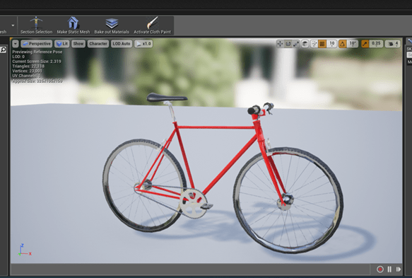
This examples provides the workflow for animating a bicycle actor. The general workflow is adapted from the Unreal Engine Vehicle User Guide.
Set up Simulink Model
Step 1: Set up Simulink Model
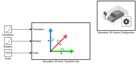
Open a new Simulink® model and add these blocks:
Two Ramp blocks
Constant block
Simulation 3D Actor Transform Set block
Simulation 3D Scene Configuration block
Connect and name the blocks as shown.
Step 2: Configure Blocks
Configure blocks with these parameter settings.
| Block | Parameter Settings |
|---|---|
Simulation 3D Scene Configuration |
|
Simulation 3D Actor Transform Set |
|
Translation Ramp |
|
Rotation Ramp |
|
Scale Constant |
|
Set up Unreal Editor to Animate Bicycle
Step 3: Set up Animation Instance
In your Simulink model, use the Simulation 3D Scene Configuration block Open Unreal Editor parameter to open the Unreal Editor.
Select Tools > New C++ Class. In the Choose Parent Class dialog box, select All Classes. Search for
AnimInst. Select theAnimInstanceand click Next.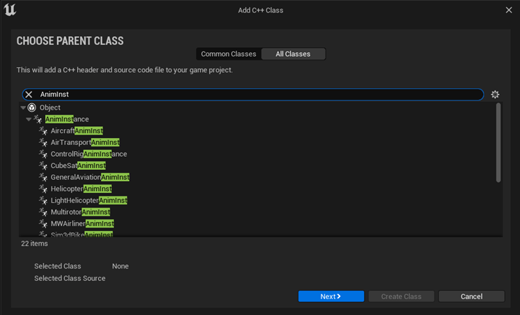
Name the new C++ class
SimulinkBikeAnimInst. Select Public. Click Create Class.
In Visual Studio 2022, open the
C:\Local\AutoVrtlEnv\AutoVrtlEnv.slnfile. Navigate to theSimulinkBikeAnimInst.cppandSimulinkBikeAnimInst.hsource files.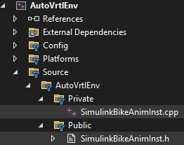
Edit the files as shown.
Tip
For this example, the code includes
FWheelRotationandRWheelRotationproperties to animate the bicycle wheel rotation. You can add additional properties to animate other parts of the bicycle.In the Unreal Editor click Compile.

Step 4: Create Animation Blueprint
In the Unreal Editor, on the Content Browser tab, under View Options, select Show Engine Content and Show Plugin Content.
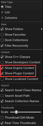
Add the animation mesh. On the Content Browser tab, navigate to MathWorksInterface Content > Vehicles > Bicyclist > Meshes.
Right-click Meshes and select Add/Import Content > Animation > Animation Blueprint.

In the Create Animation Blueprint dialog box, select:
Parent Class:
SimulinkBikeAnimInst
Target Skeleton:
SK_Bicycle_Skeleton
Click Create.
Name the blueprint
BikeAnimation. Right-click and select Save.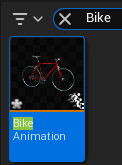
Double-click to open the
BikeAnimationblueprint. Make the connections as shown.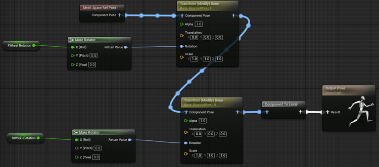
Note
For
FWheel RotationandRWheel Rotation, selectGet FWheel RotationandGet RWheel Rotationblueprint nodes, respectively.For both front and rear wheels, make sure that you set:
Bone to Modify to the correct bone
Rotation Mode to
Replace ExistingRotation Space to
Bone Space
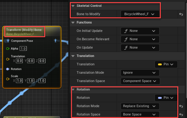
Compile and save the blueprint.
Step 5: Create Bicycle Actor C++ Class
In the Unreal Editor, on the Content Browser tab, under View Options, select Show Engine Content and Show Plugin Content.

From the MathWorks Interface C++ Classes folder, select Sim3dActor.
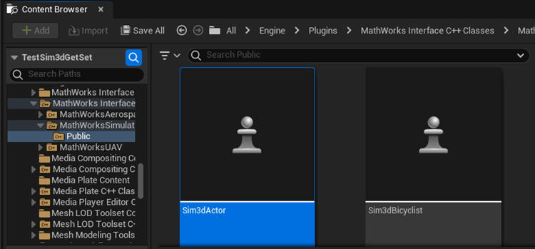
Right-click and select Create C++ class derived from Sim3dActor.
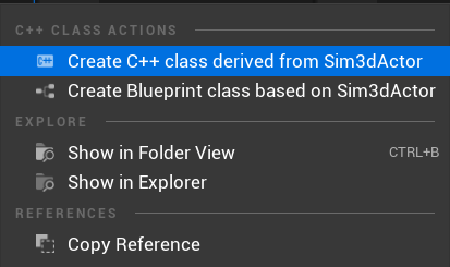
Tip
If you do not see the MathWorks Interface C++ Classes folder, use these steps to check that you have the
MathWorks Interfaceplugin installed and enabled:In the Unreal Editor toolbar, select Edit > Plugins.
In the Plugins window, verify that the MathWorks Interface plugin is listed in the installed window. If the plugin is not already enabled, select the Enabled check box.
Close the editor and reopen it from Simulink.
Name the new Sim3dActor
BicycleActor. Select Public. Click Create Class.
In Visual Studio, navigate to
BicycleActor.handBicycleActor.cpp.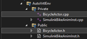
Edit the files as shown.
Tip
For this example, the code includes logic to animate the bike body (
BIKE_BODY), front wheel (FRONT_WHEEL), and rear wheel (REAR_WHEEL). You can add additional logic to animate other parts of the bicycle.In the Unreal Editor click Compile.

Step 6: Instantiate the Bicycle Actor
In your Simulink model, use the Simulation 3D Scene Configuration block Open Unreal Editor parameter to open the Unreal Editor.
Open the level
HwStraight. Select File > Open Level and selectHwStraight. Place the Bicycle Actor in the scene.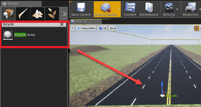
Set the tag to the same value as the Simulation 3D Actor Transform Set block Tag for actor in 3D scene, ActorTag. For this example, set the value to
Bike1.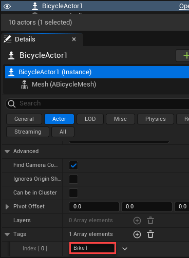
Set up Camera View (Optional)
Optionally, set up a camera view to override the default view. You can use either Simulink or a level blueprint to set up the camera view. For the recommended option, use Simulink.
Step 7: Use Simulink (Recommended)
To setup a camera view that follows along with the bicycle:
Add these blocks to the model.
One Ramp block
One Add block
Three Constant blocks
Simulation 3D Actor Transform Set block
Connect and name the blocks as shown.
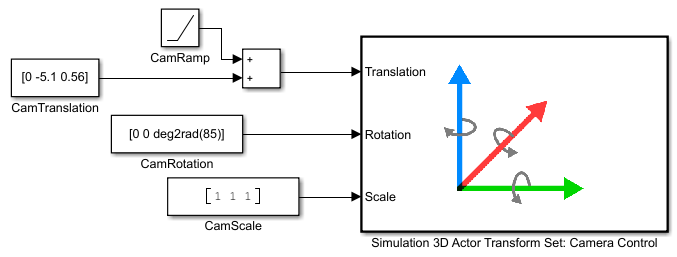
Set these block parameters.
Block Parameter Settings Simulation 3D Actor Transform Set: Camera Control
Tag for actor in 3D scene, ActorTag —
MainCamera1
CamTranslation
Constant value —
[0 -5.1 0.56]Interpret vector parameters as 1-D —
off
CamRotation
Constant value —
[0 0 deg2rad(85)]Interpret vector parameters as 1-D —
off
CamScale
Constant value —
[1 1 1]Interpret vector parameters as 1-D —
off
Step 7: Use Level Blueprint
To override the default camera view:
Add a camera actor. Assign it as a child of the BicycleActor.
Use the Transform settings to specify the location and viewing angle.
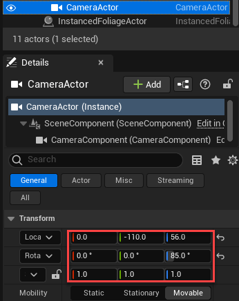
Open the level blueprint.
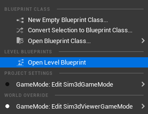
In the level blueprint, make these connections. If you right-click on the Event Graph to find nodes, clear Context Sensitive. If you have a CameraActor, you can drag it to the Event Graph from the World Outliner view in the editor.
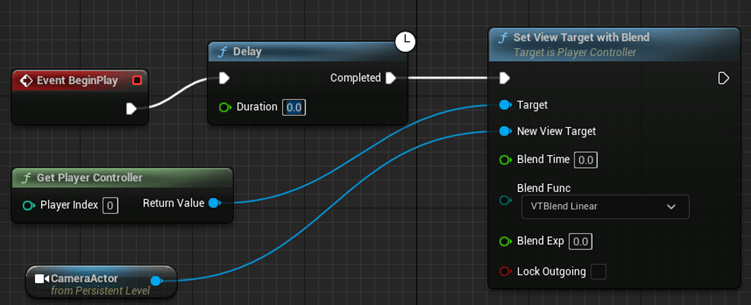
Save the blueprint and project. Close the Unreal Editor.
Run Simulation
After you configure the Simulink model and Unreal Editor environment, run a simulation.
In your Simulink model, make sure that you have set the Simulation 3D Scene Configuration parameters to these values:
Scene source —
Unreal
                        Editor
Project — Name and location of the installed support package project file, for example,
C:\Local\AutoVrtlEnv\AutoVrtlEnv.uproject.Scene view —
Scene Origin
Use the Simulation 3D Scene Configuration block Open Unreal Editor parameter to open the Unreal Editor.
Run the simulation.
In the Simulink model, click Run.
Because the source of the scenes is the project opened in the Unreal Editor, the simulation does not start.
Verify that the Diagnostic Viewer window in Simulink displays this message:
In the Simulation 3D Scene Configuration block, you set the scene source to 'Unreal Editor'. In Unreal Editor, select 'Play' to view the scene.This message confirms that Simulink has instantiated the vehicles and other assets in the Unreal Engine 3D environment.
In the Unreal Editor, click Play. The simulation runs in the scene currently open in the Unreal Editor.
See Also
Simulation 3D Actor Transform Set | Simulation 3D Scene Configuration
Topics
- Get Started Communicating with the Unreal Engine Visualization Environment
- Place Cameras on Actors in the Unreal Editor
